


Reelmaster 3550−D Page 5 − 41 Electrical System
Hydraulic Solenoid Valve Coils
The Reelmaster 3550−D hydraulic control manifolds
use several hydraulic solenoid valve coils for system
control. The lift manifold includes four (4) solenoid
valves (S1, S2, S3, and S4). The mow manifold includes
a single solenoid valve (PRV).
The TEC controller energizes and monitors the opera-
tion of the solenoid coils when specific input conditions
are met. When the solenoid coils are energized, hydrau-
lic valve shift occurs to control hydraulic circuit flow.
Testing of the coils can be done with the coil installed on
the hydraulic valve.
Testing
1. Park machine on a level surface, lower cutting units,
stop engine, engage parking brake and remove key
from the ignition switch.
2. Before disconnecting and testing solenoid valve
coils, test the TEC controller outputs with the Diagnostic
Display (see Diagnostic Display in this chapter). If out-
put testing verifies that the TEC is energizing the solen-
oid coil circuit under the appropriate conditions, leave
the diagnostic display connected and test the specific
circuit wiring.
3. Test the circuit wiring:
A. Lift hinged access cover in front of operator’s seat
and locate valve coil that is to be tested.
B. Disconnect wire harness connector from the coil.
C. Position the necessary input(s) to illuminate the
appropriate output LED indicating that the TEC con-
troller is energizing that function (see Table 3: Input
Conditions Required to Illuminate Diagnostic Dis-
play Outputs in this chapter).
D. Connect multimeter (DC voltage setting) across
the terminals of the disconnected wire harness con-
nector. 12VDC should be present at the connector
when the appropriate LED is illuminated.
E. Repair damaged wiring as necessary.
4. If the circuit wiring is functioning correctly, use the fol-
lowing procedure to test the solenoid coil(s).
A. Determine solenoid coil(s) that is to be tested and
locate coil on correct hydraulic manifold. Access the
manifolds through the hinged access panel in front of
the operator’s seat. The lift control manifold is on the
right side of the machine and the mow control mani-
fold is on the right side of the machine.
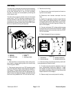
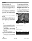
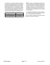
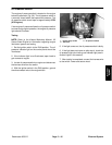
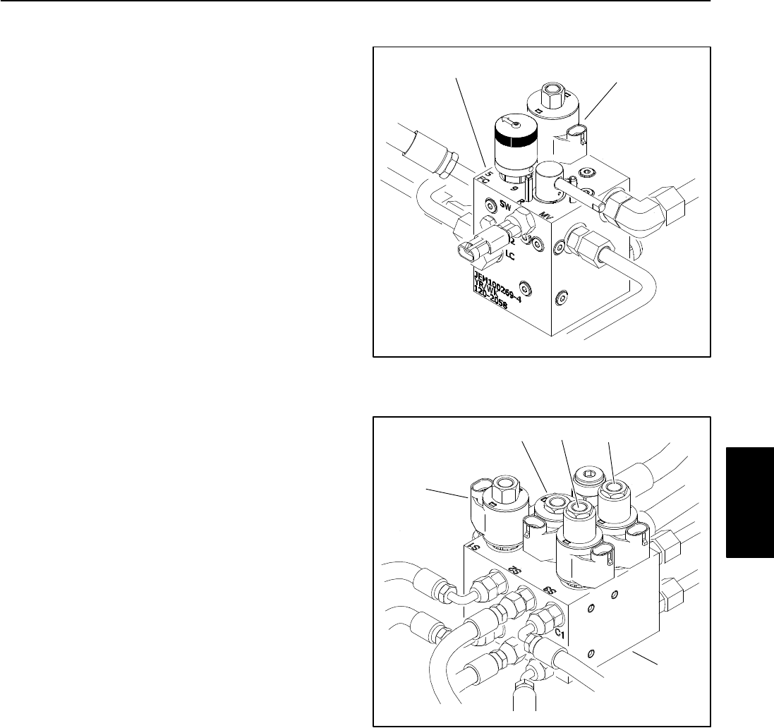
1. Mow control manifold 2. PRV solenoid valve
Figure 44
1
2
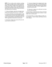
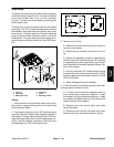
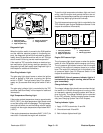
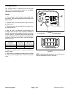
1. Lift control manifold
2. S1 solenoid valve
3. S2 solenoid valve
4. S3 solenoid valve
5. S4 solenoid valve
Figure 45
1
2
34 5
B. Disconnect wire harness connector from the hy-
draulic solenoid valve coil that is to be tested (Figs.
44 or 45).
NOTE: Prior to taking small resistance readings
with a digital multimeter, short the meter test leads to-
gether. The meter may display a small resistance
value (usually 0.5 ohms or less). This resistance is
due to the internal resistance of the meter and test
leads. Subtract this value from the measured value
of the solenoid coil being testing.
Electrical
System