


Reelmaster 3550−D Hydraulic SystemPage 4 − 31
Testing
The most effective method for isolating problems in the
hydraulic system is by using hydraulic test equipment
such as pressure gauges and flow meters in the various
hydraulic circuits to perform various operational checks
(See the Special Tools section in this chapter).
Remember that pressure specifications that appear on
hydraulic schematics are the design specifications for
the specific component. Actual system pressure will
vary depending on oil temperature, the location of the
test port, and the specific components used in the hy-
draulic circuit.
IMPORTANT: The hydraulic test procedures listed
in this manual represent actual performance for this
machine. To correctly measure product or compon-
ent performance, be sure to follow the test proced-
ures provided.
Before Performing Hydraulic Tests
All obvious areas such as fluid supply, filter, binding link-
ages, loose fasteners, or improper adjustments must be
checked before assuming that a hydraulic component is
the source of the problem.
Precautions for Hydraulic Testing
WARNING
Keep body and hands away from pin hole leaks
or nozzles that eject hydraulic fluid under high
pressure. Do not use hands to search for
leaks; use paper or cardboard. Hydraulic fluid
escaping under pressure can have sufficient
force to penetrate the skin and cause serious
injury. If fluid is injected into the skin, it must
be surgically removed within a few hours by a
doctor familiar with this type of injury. Gan-
grene may result from such an injury.
CAUTION
Failure to use gauges with recommended pres-
sure (psi) rating as listed in test procedures
could result in damage to the gauge and possible
personal injury from leaking hot hydraulic fluid.
CAUTION
All testing should be performed by two (2)
people. One person should be in the seat to oper-
ate the machine, and the other should read and
record test results.
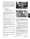
1. Clean machine thoroughly before disconnecting or
disassembling any hydraulic components. Always keep
in mind the need for cleanliness when working on hy-
draulic equipment. Hydraulic fluid contamination will
cause excessive wear of components.
2. Put metal caps or plugs on any hydraulic lines left
open or exposed during testing or while hydraulic com-
ponents are removed.
WARNING
Before disconnecting or performing any work
on the hydraulic system, all pressure in the
system must be relieved. See Relieving Hy-
draulic System Pressure in the General Infor-
mation section.
3. The engine must be in good operating condition. Use
a phototach (non−contact tachometer) when performing
a hydraulic test. Engine speed can affect the accuracy
of the test readings. Monitor engine RPM during hy-
draulic testing. Use the information below when per-
forming hydraulic system tests. If engine RPM is above
or below the specified speed during a test, you will need
to adjust the expected hydraulic performance paramet-
ers (aprox. 3% per 100 engine rpm at full throttle)
IMPORTANT: Hydraulic component output volume
relates directly to engine RPM. For every 100 engine
rpm the following component output volumes will
change by the volume listed.
Hydrostat: 100 engine RPM = 0.59 GPM or 76.6 oz.
(2265 cc) of hydraulic fluid displaced per minute
Gear Pump (P1): 100 engine RPM = 0.24 GPM or
30.8 oz. (912 cc) of hydraulic fluid displaced per
minute
Gear Pump (P2): 100 engine RPM = 0.14 GPM or
17.5 oz. (519 cc) of hydraulic fluid displaced per
minute
Hydraulic
System