


Operating Basics
AWG610 Arbitrary Waveform Generator User Manual
2-29
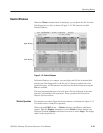
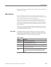
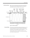
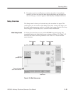
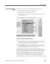
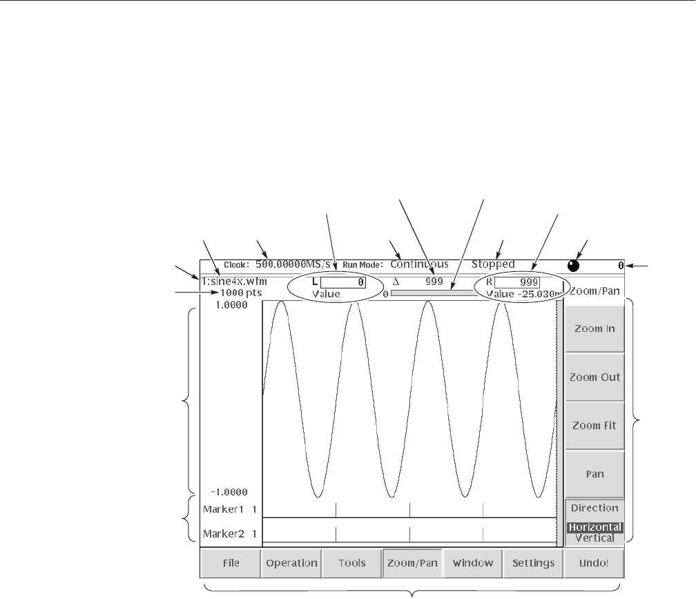
Figure 2–21 shows elements that are common to many of the editor screens.
What elements are in an editor depends on which editor is open. The Reference
section describes each editor in detail. Refer to Figure 2–21 to familiarize
yourself with the common screen elements of most of the editors.
Window number
Waveform
record length
Waveform
file name
Clock
frequency
Run
mode
Data edit/display area
Marker display
Status
display area
Knob icon
Active
cursor
position
Left cursor
position
field and
data value
Bottom menu
Side
menu
CursorĆtoĆcursor
distance
(edit area)
Position of data
viewed in overall
waveform record
Right cursor
position
field and
data value
Figure 2-21: Editor screen elements
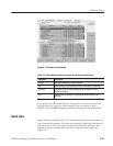
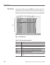
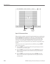
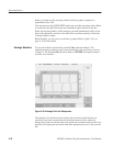
The edit window cursors define the data affected by all edit operations except the
Tools menu commands. Most of the edit commands affect the data located
between the left and right cursor positions. This region is called the edit area or
scope. Figure 2–22 shows an example of an edit area. In this example, all data is
located from left cursor position 300 to right cursor position 779.
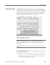
Other edit operations use the active (selected) cursor position for inserting
waveform data. The active cursor is shown as a solid vertical line. The inactive
cursor is shown as a dashed vertical line.
Editor Screen Elements
Cursors and Editing