Table of Contents
viii
AWG610 Arbitrary Waveform Generator User Manual
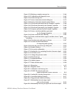
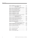
Figure 3–16: Operating data bits (scope) 3–84. . . . . . . . . . . . . . . . . . . . . . .
Figure 3–17: Area cursors 3–86. . . . . . . . . . . . . . . . . . . . . . . . . . . . . . . . . . . .
Figure 3–18: Counter dialog box 3–87. . . . . . . . . . . . . . . . . . . . . . . . . . . . . .
Figure 3–19: Set Pattern dialog box 3–88. . . . . . . . . . . . . . . . . . . . . . . . . . .
Figure 3–20: A waveform example under quick editing 3–92. . . . . . . . . . .
Figure 3–21: Controls for quick editing 3–93. . . . . . . . . . . . . . . . . . . . . . . .
Figure 3–22: Table Editor window 3–100. . . . . . . . . . . . . . . . . . . . . . . . . . . . .
Figure 3–23: Equation editor window 3–104. . . . . . . . . . . . . . . . . . . . . . . . . .
Figure 3–24: Text selection (example) 3–107. . . . . . . . . . . . . . . . . . . . . . . . . .
Figure 3–25: File list listing two waveforms created 3–110. . . . . . . . . . . . . .
Figure 3–26: Sequence editor initial screen 3–111. . . . . . . . . . . . . . . . . . . . .
Figure 3–27: EVENT IN connector 3–118. . . . . . . . . . . . . . . . . . . . . . . . . . . .
Figure 3–28: Event signal timing and strobe 3–121. . . . . . . . . . . . . . . . . . . .
Figure 3–29: Compiling and storing sequences and subsequences 3–123. . .
Figure 3–30: Outline flow for producing HDD reading test signal 3–125. . .
Figure 3–31: Disk application initial screen 3–126. . . . . . . . . . . . . . . . . . . . .
Figure 3–32: Writer Data menu 3–126. . . . . . . . . . . . . . . . . . . . . . . . . . . . . . .
Figure 3–33: Isolated Pulse menu 3–127. . . . . . . . . . . . . . . . . . . . . . . . . . . . .
Figure 3–34: Execution of superpose 3–127. . . . . . . . . . . . . . . . . . . . . . . . . . .
Figure 3–35: Outline flow for producing network test read signal 3–134. . .
Figure 3–36: Network application initial screen 3–134. . . . . . . . . . . . . . . . . .
Figure 3–37: Side menu will change after selecting a standard 3–135. . . . .
Figure 3–38: Side menu for selecting the Isolated pulse 3–136. . . . . . . . . . .
Figure 3–39: Execution of superposing 3–137. . . . . . . . . . . . . . . . . . . . . . . . .
Figure 3–40: Outline flow for Jitter waveform creation 3–141. . . . . . . . . . .
Figure 3–41: Jitter composer application initial screen 3–142. . . . . . . . . . . .
Figure 3–42: Input Data menu 3–142. . . . . . . . . . . . . . . . . . . . . . . . . . . . . . . .
Figure 3–43: A pre-defined pattern was selected as an input data 3–143. . .
Figure 3–44: Jitter profile menu 3–143. . . . . . . . . . . . . . . . . . . . . . . . . . . . . .
Figure 3–45: Execution of jitter composer 3–144. . . . . . . . . . . . . . . . . . . . . .
Figure 3–46: Jitter parameters and jitter waveform 3–147. . . . . . . . . . . . . .
Figure 3–47: GPIB setup screen menu 3–154. . . . . . . . . . . . . . . . . . . . . . . . .
Figure 3–48: Network setup screen menu 3–156. . . . . . . . . . . . . . . . . . . . . . .
Figure 3–49: Message box to indicate the establishment
of communication 3–158. . . . . . . . . . . . . . . . . . . . . .
Figure 3–50: Network Status screen 3–158. . . . . . . . . . . . . . . . . . . . . . . . . . .
Figure 3–51: UTILITY screen mounting remote file system 3–159. . . . . . .
Figure 3–52: Drive selections in EDIT menu 3–160. . . . . . . . . . . . . . . . . . . .
Figure 3–53: Hardcopy setup screen 3–163. . . . . . . . . . . . . . . . . . . . . . . . . . .


