


1-34
Introduction
Interface Functions
Interface Functions
The interface functions deal with general bus management issues, as well as messages that
can be sent over the bus as bus commands. In general, these functions are defined by IEEE
488.1. The instrument is equipped with a GPIB interface connector on the rear panel. This
allows direct connection to a GPIB equipped computer. You can connect an external GPIB
compatible device to the instrument by installing a GPIB cable between the two units. Finger
tighten the captive screws on both ends of the GPIB cable to avoid accidentally disconnecting
the cable during operation. A maximum of fifteen GPIB compatible instruments (including a
computer) can be interconnected in a system by stacking connectors. This allows the instru-
ments to be connected in virtually any configuration, as long as there is a path from the com-
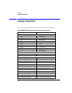
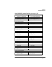
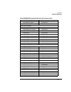
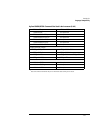
puter to every device operating on the bus. The interface capabilities of this instrument, as
defined by IEEE 488.1, are listed in the Table 1-9 on page 1-35.
CAUTION Avoid stacking more than three or four cables on any one connector. Multiple connectors produce leverage that
can damage a connector mounting.
GPIB Default
Startup
Conditions
The following default GPIB conditions are established during power-up: 1) The Request Ser-
vice (RQS) bit in the status byte register is set to zero. 2) All of the event registers, the Stan-
dard Event Status Enable Register, Service Request Enable Register, and the Status Byte
Register are cleared.
Command and
Data Concepts
The GPIB has two modes of operation, command mode and data mode. The bus is in the com-
mand mode when the Attention (ATN) control line is true. The command mode is used to
send talk and listen addresses and various bus commands such as group execute trigger
(GET). The bus is in the data mode when the ATN line is false. The data mode is used to con-
vey device-dependent messages across the bus. The device-dependent messages include all
of the instrument specific commands, queries, and responses found in this manual, including
instrument status information.
Communicating
Over the Bus
Device addresses are sent by the computer in the command mode to specify who talks and
who listens. Because GPIB can address multiple devices through the same interface card, the
device address passed with the program message must include the correct interface select
code and the correct instrument address.
Device Address = (Interface Select Code * 100) + (Instrument Address)
The examples in this manual assume that the instrument is at device address 707. Each inter-
face card has a unique interface select code. This code is used by the computer to direct com-
mands and communications to the proper interface. The default is typically “7” for GPIB
interface cards. Each instrument on the GPIB must have a unique instrument address