1-19
Introduction
Status Reporting
Standard Event
Status Enable
Register
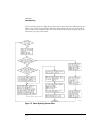
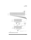
For any of the Standard Event Status Register (SESR) bits to generate a summary bit, you
must first enable the bit. Use the *ESE (Event Status Enable) common command to set the
corresponding bit in the Standard Event Status Enable Register. Set bits are read with the
*ESE? query. Suppose your application requires an interrupt whenever any type of error
occurs. The error status bits in the Standard Event Status Register are bits 2 through 5. The
sum of the decimal weights of these bits is 60. Therefore, you can enable any of these bits to
generate the summary bit by sending:
OUTPUT 707;"*ESE 60"
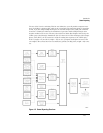
Whenever an error occurs, the instrument sets one of these bits in the Standard Event Status
Register. Because the bits are all enabled, a summary bit is generated to set bit 5 (ESB) in the
Status Byte Register. If bit 5 (ESB) in the Status Byte Register is enabled (via the *SRE com-
mand), a service request interrupt (SRQ) is sent to the external computer.
NOTE Disabled SESR Bits Respond, but Do Not Generate a Summary Bit. Standard Event Status Register bits that are
not enabled still respond to their corresponding conditions (that is, they are set if the corresponding event
occurs). However, because they are not enabled, they do not generate a summary bit in the Status Byte Register.
User Event
Register (UER)
This register hosts the LCL bit (bit 0) from the Local Events Register. The other 15 bits are
reserved. You can read and clear this register using the UER? query. This register is enabled
with the UEE command. For example, if you want to enable the LCL bit, you send a mask
value of 1 with the UEE command; otherwise, send a mask value of 0.
Local Event
Register (LCL)
This register sets the LCL bit in the User Event Register and the USR bit (bit 1) in the Status
byte. It indicates a remote-to-local transition has occurred. The LER? query is used to read
and to clear this register.
Operation Status
Register (OPR)
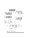
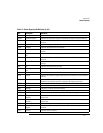
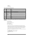
This register hosts the CLCK bit (bit 7), the LTEST bit (bit 8), the ACQ bit (bit 9) and the
MTEST bit (bit 10). The CLCK bit is set when any of the enabled conditions in the Clock
Recovery Event Register have occurred. The LTEST bit is set when a limit test fails or is com-
pleted and sets the corresponding FAIL or COMP bit in the Limit Test Events Register. The
ACQ bit is set when the COMP bit is set in the Acquisition Event Register, indicating that the
data acquisition has satisfied the specified completion criteria. The MTEST bit is set when
the Mask Test either fails specified conditions or satisfies its completion criteria, setting the
corresponding FAIl or COMP bits in the Mask Test Events Register. The PTIME bit is set
when there is a loss of the precision timebase reference occurs setting a bit in the Precision
Timebase Events Register. The JIT bit is set in Jitter Mode when a bit is set in the Jitter
Events Register. This occurs when there is a failure or an autoscale is needed. If any of these
bits are set, the OPER bit (bit 7) of the Status Byte register is set. The Operation Status Reg-
ister is read and cleared with the OPER? query. The register output is enabled or disabled
using the mask value supplied with the OPEE command.


