25-9
Waveform Commands
SOURce
SOURce
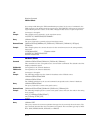
Command :WAVeform:SOURce {WMEMory<N> | FUNCtion<N> | CHANnel<N> | HISTogram | RESPonse<N> | CGRade}
This command selects a channel, function, TDR response, waveform memory, histogram, or
color grade/gray scale as the waveform source. If the waveform source is set to CGRade, the
default source is the first database signal displayed. To set the CGRade source you must use
the :WAVeform:SORUce:CGRade command. TDR responses are valid sources for waveform
queries only if the current settings for channel bandwidth, record length, and timebase match
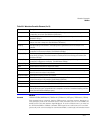
Y Increment The Y increment is the duration between Y-axis levels. For voltage waveforms, it is the voltage
corresponding to one level. (See WAVeform:YINCrement.)
Y Origin The Y origin is the Y-axis value at level zero. For voltage signals, it is the voltage at level zero. (See
WAVeform:YORigin.)
Y Reference The Y reference is the level associated with the Y origin. It is at this level that the Y origin is defined. In this
analyzer, this value is always zero. (See WAVeform:YREFerence.)
Coupling The input coupling of the waveform. The coupling value is ignored when sent to the analyzer in the
preamble.
X Display Range The X display range is the X-axis duration of the waveform that is displayed. For time domain signals, it is
the duration of time across the display. (See WAVeform:XRANge.)
X Display Origin The X display origin is the X-axis value at the left edge of the display. For time domain signals, it is the time
at the start of the display. This value is treated as a double precision 64-bit floating point number. (See
WAVeform:XDISplay.)
Y Display Range The Y display range is the Y-axis duration of the waveform which is displayed. For voltage waveforms, it is
the amount of voltage across the display. (See WAVeform:YRANge.)
Y Display Origin (See WAVeform:YDISplay.)
Date The date that the waveform was acquired or created.
Time The time that the waveform was acquired or created.
Frame Model # The model number of the frame that acquired or created this waveform. The frame model number is ignored
when it is sent to an analyzer in the preamble.
Acquisition Mode The acquisition sampling mode of the waveform.
Complete The complete value is the percent of time buckets that are complete. The complete value is ignored when it
is sent to the analyzer in the preamble. (See WAVeform:COMPlete.)
X Units The X-axis units of the waveform. (See WAVeform:XUNits.)
Y Units The Y-axis units of the waveform. (See WAVeform:YUNits.)
Band Pass The band pass consists of two values that are an estimation of the maximum and minimum bandwidth
limits of the source signal. The bandwidth limit is computed as a function of the selected coupling and filter
mode. (See the WAVeform:BANDpass query.)
Table 25-1. Waveform Preamble Elements (2 of 2)
Element Description


