22-3
TDR/TDT Commands (Rev. A.06.00 and Above)
Module Channel
Identification
In previous software revisions, each TDR/TDT subsystem command identified the TDR mod-
ule installation (left or right mainframe slot) with the form :TDR{2:4}:<command>. Starting with
software revision A.06.00, the TDR/TDT subsystem no longer uses this identification scheme;
the new syntax form is simply :TDR:<command>.
TDR/TDT
Calibration
TDR/TDT calibration corrects for measurement system effects and locates the reference
plane of the step response. The reference plane is the time (or distance) of the incident step
and is the location that all subsequent impedance measurements are made relative to. Start-
ing with software revision A.06.00 and above, TDR/TDT Calibration replaces the normaliza-
tion and reference plane calibration. TDR/TDT Calibration allows marker time readouts
relative to the reference plane but, in addition, adds the ability to change the time base set-
ting, corrects for systematic errors, and enables a pulse rise time filter to simulate real step
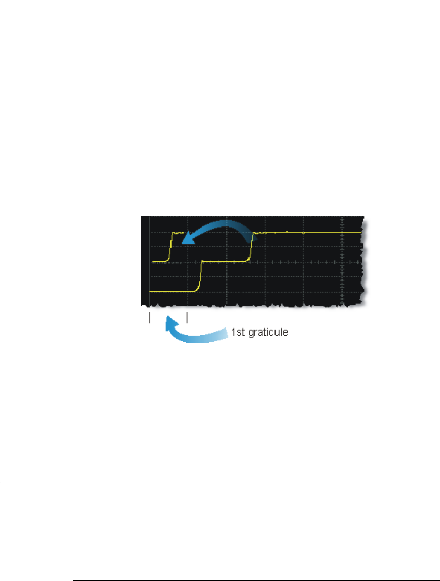
responses. For best results, before starting the TDR/TDT calibration place the step response
at the reference plane within the first graticule division as shown the following picture.
The calibration commands step through the TDR/TDT Calibration Wizard. Send
“RESPonse:CALibrate” on page 22-5 followed by “SDONe?” on page 7-9 to begin the calibra-
tion. Use the returned string from the SDONe? query to determine when a calibration step
has completed. If you set a time out value, make sure that the value is set long enough to
allow the measurement to complete. SDONe? returns the prompt string for the next step.
After making the test setup connections for a calibration step, send “CONTinue” on page 7-4
followed by SDONe?. At the end of the last step, SDONe? returns the string “Done”.
NOTE Once the module calibration procedure is started, all access to the instrument’s front panel is blocked, including
the use of the Local button. Pressing Local during a module calibration will not place the instrument in local
mode. The calibration must either be cancelled (using “CANCel” on page 7-4) or finished before you can regain
control to the instrument’s front panel. Failure of a calibration step results in that step being repeated.
More Information Option 202 TDR Peeling is implemented as a math function. Refer to “PEELing” on
page 12-7. To perform the measurements that are listed on the measurement toolbar, refer to
Chapter 18, “Measure Commands”.


