


Groundsmaster 5900/5910 Hydraulic SystemPage 4 -- 27
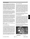
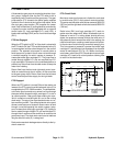
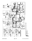
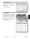
Steering Circuit
A three section gear pump is coupled to the piston (trac-
tion) pump. The gear pump section (P3) farthest from
the piston pump supplies hydraulic flow to the steering/
cooling fan control manifold, the lift control manifold and
the traction charge circuit. Hydraulic flow from pump
section (P3) is split between the steering/cooling fan/
charge circuit and the lift/lower circuit by a proportional
flow divider located in the lift control manifold. This flow
divider splits pump flow approximately 75% for the
steering/cooling fan/charge circuit (10.5 GPM/39.7
LPM) and 25% for the lift/lower circuit (3.5 GPM/13.2
LPM).
The steering/cooling fan control manifold controls the
operation of the steering control valve and the gear mo-
tor that drives the engine cooling fan. Priority valve (PV)
in the manifold controls the oil flow to the steeringcontrol
valve which is a closed center, load sensing valve. The
steering control valve senses the oil flow that is needed
for steering and the priority valve (PV) will supply the
correct amount. Oil not used by steering is provided to
thecoolingfanmotor.
With the steering wheel in the neutral, at rest position
and the engine running, hydraulic oil from the lift control
manifold flow divider enters the steering/cooling fan
control manifold port P, flows through the priority valve
(PV) and to the steering control valve where it dead
heads at the spool. Oil is also sent to both ends of the
(PV) spool. On one end of the spool, oil is directed to the
steering relief valve (RV) and also is directed through
the OR orifice and out the LS manifold port to the steer-
ing control valve. This flow provides steering load sense
pressure and is directed through a small passage in the
steering control valve spool and sleeve before returning
to the charge circuit. While this load sense pressure is
returning to the charge circuit, the priority valve (PV)
spool shifts to direct pump flow to the engine fan motor
circuit. Without steering input, no oil is flowing through
the steering control valve.
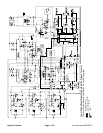
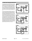
Left Turn
When a left turn is made with the engine running, the
turningofthesteering wheel positions the spool valve so
that the load sense flow is blocked off. Without load
sense flow, pressures on the ends of manifold priority
valve(PV)starttoequalizecausing(PV)tomovetoward
its neutral position which allows the needed oil to the
steering control valve. Oil is routed out manifold port CF,
into steering valve port P, through the steering control
spool, is drawn through the rotary meter section and out
the L port to the steering cylinders. The rotary meter en-
sures that the oil flow to the cylinders is proportional to
the amount of the turning on the steering wheel. Fluid
leaving the cylinders flows back through steering valve
R port, the spool valve, out the T port and is then used
for traction circuit charge oil.
The steering wheel and steering control valve return to
the neutral position when turning is completed.
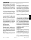
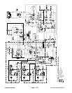
Right Turn
When a right turn is made with the engine running, the
turningofthesteering wheel positions the spool valve so
that the load sense flow is blocked off. Without load
sense flow, pressures on the ends of manifold priority
valve(PV)starttoequalizecausing(PV)tomovetoward
its neutral position which allows the needed oil to the
steering control valve. Oil is routed out manifold port CF,
into steering valve port P, through the steering control
spool, is drawn through the rotary meter section and out
the R port to the steering cylinders. The rotary meter en-
sures that the oil flow to the cylinders is proportional to
the amount of the turning on the steering wheel. Fluid
leaving the cylinders flows back through the steering
valve L port, the spool valve, out the T port and is then
used for traction circuit charge oil.
The steering wheel and steering control valve return to
the neutral position when turning is completed.
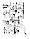
Steering Relief Operation
Whenthesteeringcylindersreachtheend of their stroke
or if a rear wheel should encounter an obstruction (e.g.
acurb)whilesteering,thepressure in the steering circuit
will rise. R elief valve (RV) in the steering/cooling fan
control manifold senses this pressure increase. When
this pressure builds to approximately 2100 PSI (145
bar), relief valve (RV) opens and allows hydraulic flow
toreturntotank.This action causes flowacrosstherelief
valve side orifice of priority valve (PV) which s hifts the
spool in (PV) to send oil away from the steering circuit
to the fan motorcircuit. Relief v alve (RV) controls theac-
tion of priority valve (PV) and allows the priority valve to
divert only enough oil flow to the steering circuit to main-
tain relief pressure.
Hydraulic
System