


Groundsmaster 5900/5910Page 5 -- 54Electrical System
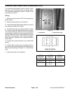
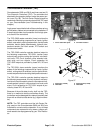
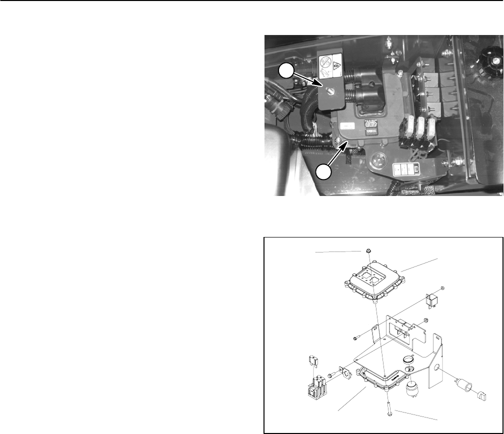
Toro Electronic Controller (TEC)
Groundsmaster 5900 and 5910 machines use two (2)
Toro Electronic Controllers (TEC). The controllers are
attached to the operator platform under the power cen-
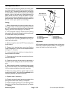
ter cover (Fig. 96). The Info Center Display should be
used when checking inputs and outputs of the TECused
on your Groundsmaster (see Troubleshooting in this
chapter).
Logic power isprovided to bothof the controllers as long
as the battery cables are connected to the batteries. A
2 amp fuse provides circuit protection for this logic pow-
er to each of the controllers.
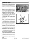
The TEC--5002 master controller (lower) monitors the
states of the following components as inputs: ignition
switch, seat switch, parking brake switch, service brake
switches, traction pedal potentiometer, hydraulic tem-
perature sender, fuel level sender, PTO switch and
cruise control switch.
The TEC--5002 controller controls electrical output to
the following components: TEC--5001, traction pump
solenoid coils, engine cooling fan hydraulic valve sole-
noid coils, PTO circuit hydraulic valve solenoid coils,
start relay and turn signals. Circuit protection for
TEC--5002 outputs is provided by fuses 3F2, 3F3 and
3F4.
The TEC--5001 slave controller (upper) monitors the
states of the following components as inputs: ignition
switch, cutting deck lift switches, traction assist switch,
mow/transportswitchand cutting deckpositionsensors.
The TEC--5001 controller controls electrical output to
the following components: lift circuit hydraulic valve so-
lenoid coils, traction assist hydraulic valve solenoid coil,
mow/transport hydraulic valve solenoid coil and audio
alarm. Circuit protection for TEC--5001 outputs is pro-
vided by fuses 4F2, 4F3 and 4F4.
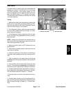
Because of the solid state circuitry built into the TEC,
there is no method to test the controllers directly. The
controllers may be damaged if an attempt is made to test
them with an electrical test device (e.g. digital multime-
ter).
NOTE: The TEC controllers and the Info Center Dis-
play used on the Groundsmaster 5900 and 5910 are
matched for correct machine operation. If any of these
components are replaced for any reason, system soft-
ware needs to be reprogrammed by your Toro Distribu-
tor.
1. Cover attachment point 2. Controller location
Figure 96
1
2
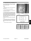
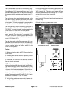
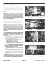
1. Flange nut (4 used)
2. TEC--5001
3. Flange screw (4 used)
4. TEC--5002
Figure 97
1
2
3
4