


Groundsmaster 5900/5910 Hydraulic SystemPage 4 -- 99
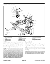
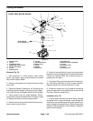
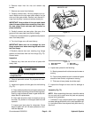
2. If removed, install woodruff key and spider hub to
motorshaft.Securewithwasherandhexnut.Torque nut
from 27 to 33 ft-- lb (37 to 44 N--m).
3. Check for proper clearance between spider hub and
spindle pulley. Install motor to cutting deck without plac-
ing the spider in the spindle pulley. The clearance be-
tween hub and pulley valleys should be from 0.830” to
0.930” (21.1 to 23.6 mm). If required, use mounting
shim(s) between motor and motor mount to adjust clea-
rance.
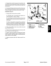
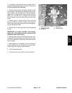
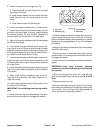
4. Position spider in spindle pulley. Place mounting
shim(s) (if required) on deck. Carefully install hydraulic
motor to the cutting deck taking care to not damage spi-
der hub attached to motor.
5. Securemotortocuttingdeckwithtwo(2)flangehead
screws.
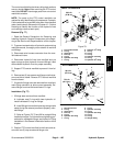
IMPORTANT: For proper hydraulic hose routing,
make sure cutting decks are fully lowered before
installing hoses to deck motor.
6. Remove caps or plugs from fittings and hoses. Con-
nect hydraulic hoses to deck motor (see Hydraulic Hose
and Tube Installation in the General Information section
of this chapter).
7. After assembly is completed, verify that hydraulic
hoses and fittings are not contacted by moving compo-
nents through full range of deck movement.
8. Install cutting deck cover.
9. Fill reservoir with new hydraulic fluid as required.
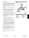
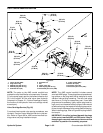
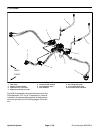
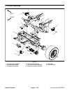
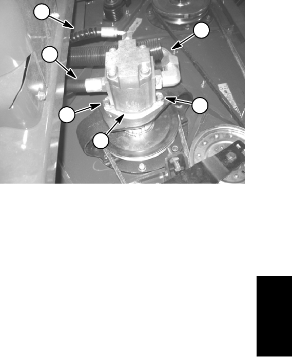
1. Deck motor (front)
2. Flange head screw
3. Inlet hose
4. Return hose
5. Case drain hose
Figure 71
2
1
3
2
5
4
Hydraulic
System