


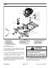
Groundsmaster 5900/5910 Page 3 -- 31 Diesel Engine
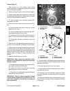
Removal (Fig. 27)
1. Park machine on a level surface, lower cutting
decks, stop engine, engage parking brake and remove
key from the ignition switch.
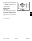
2. Raise and support hood to allow access to engine.
3. Loosen screws that secure alternator to mounting
brackets and rotate alternator toward engine to loosen
drive belt. Remove belt from machine.
4. On Groundsmaster 5910 machines, remove A/C
compressor drive belt.
5. Removeelectricalcomponentsfromfrontcover(Fig.
28):
A. Remove screws that secure electrical harness
clamps to front cover.
B. Remove screws that securecrankshaft and cam-
shaft position sensors to front cover.
C. Carefully pull two (2) sensors from front cover. In-
spect O --rings on sensors and replace if necessary.
D. Position wire harness and sensors away from
front cover.
6. Remove five (5) flange head screws that secure oil
pan to front cover ( see Oil Pan Removal in this section).
7. Remove lock nut and thrust washer that secure rear
axle pivot shaft to frame. Slide pivot shaft toward rear of
machine to allow clearance for engine pulley bolt to be
removed (see Rear Axle Removal in the Service and
Repairs section of Chapter 6-- Axles, Planetaries and
Brakes).
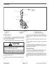
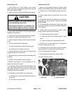
8. Remove crankshaft pulley (Fig. 28):
IMPORTANT: When removing crankshaft pulley,
take care to not damage tone wheel that is secured
to back of pulley.
A. Use appropriate holdingtool to prevent the pulley
and engine crankshaft from rotating.
B. Loosen and remove cap screw and mounting
plate that secure pulley to crankshaft.
C. Slide pulley from crankshaft. Locate and retrieve
woodruff key from crankshaft.
IMPORTANT: Three (3) different lengths of flange
head screws are used to secure the front cover. To
assist with assembly, note location of screws as
they are removed.
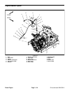
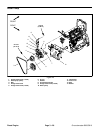
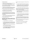
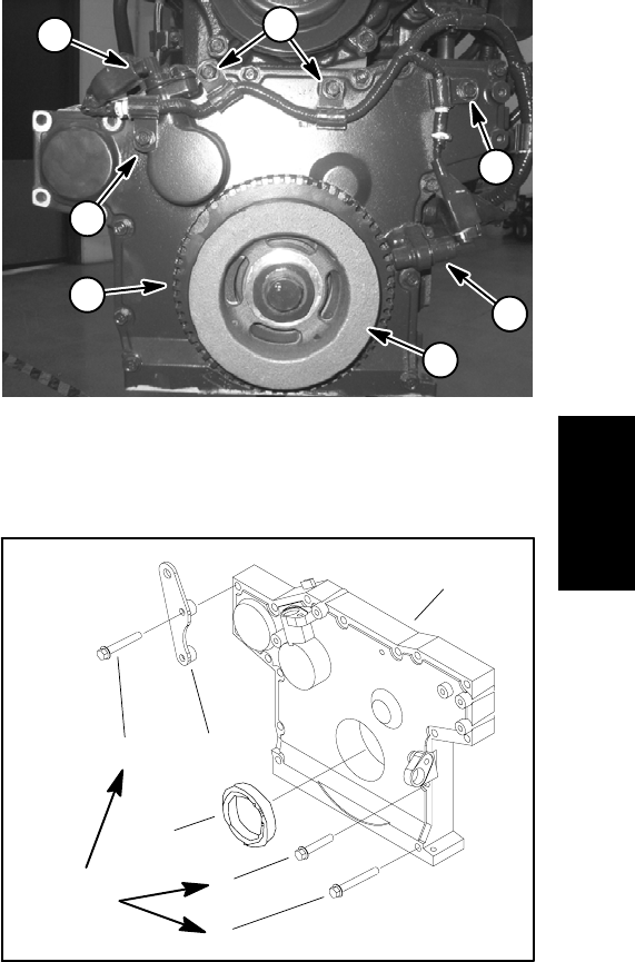
Figure 28
1. Crankshaft sensor
2. Camshaft sensor
3. Tone wheel
4. Harness clamp
5. Crankshaft pulley
1
3
2
4
4
4
5
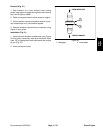
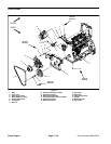
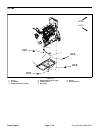
Figure 29
1. Front cover
2. Flange head screw
3. Flange head screw
4. Oil seal
5. Alternator bracket
6. Flange head screw
2
6
5
4
3
1
14 ft--lb
(19 N--m)
9. Removesixteen(16)flangeheadscrewsthatsecure
front cover to engine (Fig. 29). Rotate alternator bracket
away from front cover.
10.Carefully remove front cover from engine.
11.Remove seal from front cover taking care to notdam-
age seal bore in cover.
12.Thoroughly clean all removed components. Make
sure that all sealant is removed from front cover sealing
surfaces.
13.Inspect crankshaft surface inoilsealareaforanyevi-
dence of wear or damage. Repair or replace crankshaft
if necessary.
Diesel
Engine