


Groundsmaster 5900/5910 Page 7 -- 25 Chassis
NOTE: Most of the seat suspension components can
be serviced with the seat suspension base mounted to
the frame platform. If the air spring assembly (item 6) re-
quiresremoval,theseat suspension base will have tobe
removed from the seat platform.
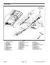
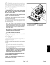
Disassembly (Fig. 21)
1. Park machine on a level surface, lower cutting
decks, stop engine, apply parking brake and remove
key from the ignition switch.
2. Remove operator seat from seat suspension (see
Operator Seat Removal in this section).
3. Disconnect seat suspension electrical connector
from machine wire harness.
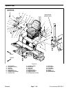
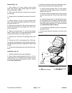
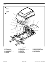
4. If the air spring assembly (item 6) or base plate (item
37) requires removal, remove seat suspension from
seat platform (Fig. 22):
A. To gain access to seat suspension mounting
screws, slide fuel tank toward left side of machine
(see Fuel Tank Removal in the Service and Repairs
section of Chapter 3 -- Engine). Support tank to pre-
vent it from shifting.
B. Remove four (4) screws and flange nuts that se-
cure seat suspension to seat platform.
C. Lift seat suspension from machine.
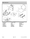
5. Remove seat suspension components as needed
using Figure 21 as a guide.
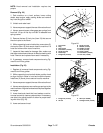
Assembly (Fig. 21)
1. Install all removed seat suspension components us-
ing Figure 21 as a guide.
2. If seat suspension was removed from seat platform
(Fig. 22):
A. Position seat suspension onto seat platform.
B. Secureseatsuspensionto seat platform with four
(4) screws and flange nuts.
C. Slide fuel tank toward right side of machine (see
Fuel Tank Installation in the Service and Repairs
section of Chapter 3 -- Engine). Make sure that fuel
tank and front wheel are properly secured.
3. Install operator seat to seat suspension (see Opera-
tor Seat Installation in this section).
4. Make sure that seat electrical connectors are se-
cured to machine wire harness.
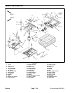
1. Operator seat assembly
2. Flange nut (4 used)
3. Screw (4 used)
4. Seat platform
Figure 22
2
3
1
4
Chassis