


Groundsmaster 5900/5910 Hydraulic SystemPage 4 -- 21
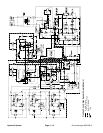
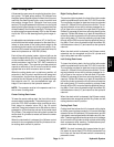
Lower Cutting Deck
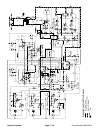
A three section gear pump is coupled to the piston (trac-
tion) pump. The gear pump section (P3) farthest from
the piston pump supplies hydraulic flow to the lift control
manifold, the steering/cooling fan control manifold and
the traction charge circuit. Hydraulic flow from pump
section (P3) is split between the lift/lower circuit and the
steering/cooling fan/chargecircuitbyaproportionalflow
divider located inthe lift control manifold. This flowdivid-
er splits pump flow approximately 25% for the lift/lower
circuit and 75% for the steering/cooling fan/charge cir-
cuit.
An adjustable counterbalance valve (LC) in the lift con-
trolmanifoldmaintains back pressureonthedeck lift cyl-
inders to allow some of the cutting deck weight to be
transferred to the traction unit to improve traction. A re-
liefvalve (RV)located in the lift control manifold limitslift/
lower circuit pressure to 1350 PSI (93 bar).
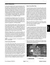
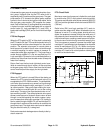
Each of the cutting decks (center, right and left) can be
lowered independently with the use of three (3) switches
on the armrest console (Fig. 11). Pressing the front of a
switch provides an input for the TEC--5001 controller to
lower a cutting deck. The controller provides electrical
outputs to solenoids in the lift control manifold to allow
appropriate valve shift to cause a deck to lower.
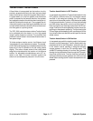
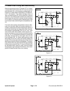
When the cutting decks are in a stationary position, all
solenoids in the lift control manifold are de--energized.
In this position, the flow from the gear pump that is pro-
portioned for the lift/lower circuit is by--passed through
the solenoid valve S1, the counterbalance logic c ar-
tridge LC and returns to the hydraulic reservoir.
NOTE: The operator must be in the operator seat in or-
der to lower a cutting deck.
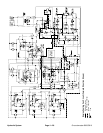
Center Cutting Deck Lower
To lower the center cutting deck, the front of the center
console switch is depressed. The switch signal is an in-
put to the TEC--5001 controller which provides an elec-
trical output to solenoid valve S6 in the lift control
manifold. Energized solenoid valve S6 shifts to allow a
passage for oil flow from the rod end of the center deck
lift cylinders. The weight of the cutting deck causes the
center deck lift cylinders to retract and lower the center
cutting deck.
When the deck switch is released, the lift/lower control
solenoid is de --energized and the lift cylinders and cen-
ter cutting deck are held in position.
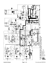
Right Cutting Deck Lower
To lower the right wing deck, the front of the right console
switch is pushed asaninput to the TEC--5001 controller.
The controller provides an electrical output to solenoid
valves S1, S8 and S9 in the lift control manifold. The en-
ergized solenoid valves shift to allow a passage for cir-
cuit oil flow to the rod end of the right deck lift cylinder.
Shifted S1 prevents oil flow from returning directly to the
reservoir. Shifted S8 allows an oil path to the shaft end
of the lift cylinder to retract the lift cylinder and lower the
right cutting deck. Oil from the retracting cylinder flows
through orifice OR2 to control the drop speed of the cut-
ting deck. Flow is then directed through the shifted S9,
counterbalance valve (LC) and returns to the hydraulic
reservoir.
When the deck switch is released, the lift/lower control
solenoids are de--energized and the lift cylinder and
right cutting deck are held in position.
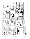
Left Cutting Deck Lower
To lower the left wing deck, the front of the left console
switch is pushed asaninput to the TEC--5001 controller.
The controller provides an electrical output to solenoid
valves S1, S3 and S4 in the lift control manifold. The en-
ergized solenoid valves shift to allow a passage for cir-
cuit oil flow to the rod end of the left deck lift cylinder.
Shifted S1 prevents oil flow from returning directly to the
reservoir. Shifted S3 allows an oil path to the shaft end
of the lift cylinder to retract the lift cylinder and lower the
left cutting deck. Oil from the retracting cylinder flows
through orifice OR1 to control the drop speed of the cut-
ting deck. Flow is then directed through the shifted S3,
counterbalance valve (LC) and returns to the hydraulic
reservoir.
When the deck switch is released, the lift/lower control
solenoids are de--energized and the lift cylinder and left
cutting deck are held in position.
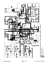
Cutting Deck Float
Cutting deck float allows the fully lowered cutting decks
to follow ground surface contours. Lift control manifold
solenoid valves S4 (left deck), S6 (center deck) and S9
(right deck) are energized when the decks are fully low-
ered.Theseenergizedsolenoidsprovideanoilpassage
to and from the lift cylinders to allow cylinder and cutting
deck movement while mowing. Counterbalance pres-
sure will affect deck float operation.
NOTE: If a deck is already fully lowered when the igni-
tion switch is moved from OFF to RUN, the deck will not
be in float until the deck lift/lower switch is momentarily
pressed to lower.
Hydraulic
System