


Groundsmaster 5900/5910Page 5 -- 32Electrical System
Component Testing
For accurate resistance and/or continuity checks, elec-
trically disconnect the component being tested from the
circuit (e.g. unplug the wire harness connector from the
ignition switch before doing a continuity check of the
switch).
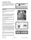
CAUTION
When testing electrical components for continu-
ity with a multimeter (ohms setting), make sure
that power to the circuit has been disconnected.
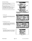
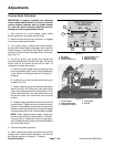
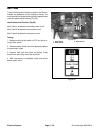
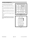
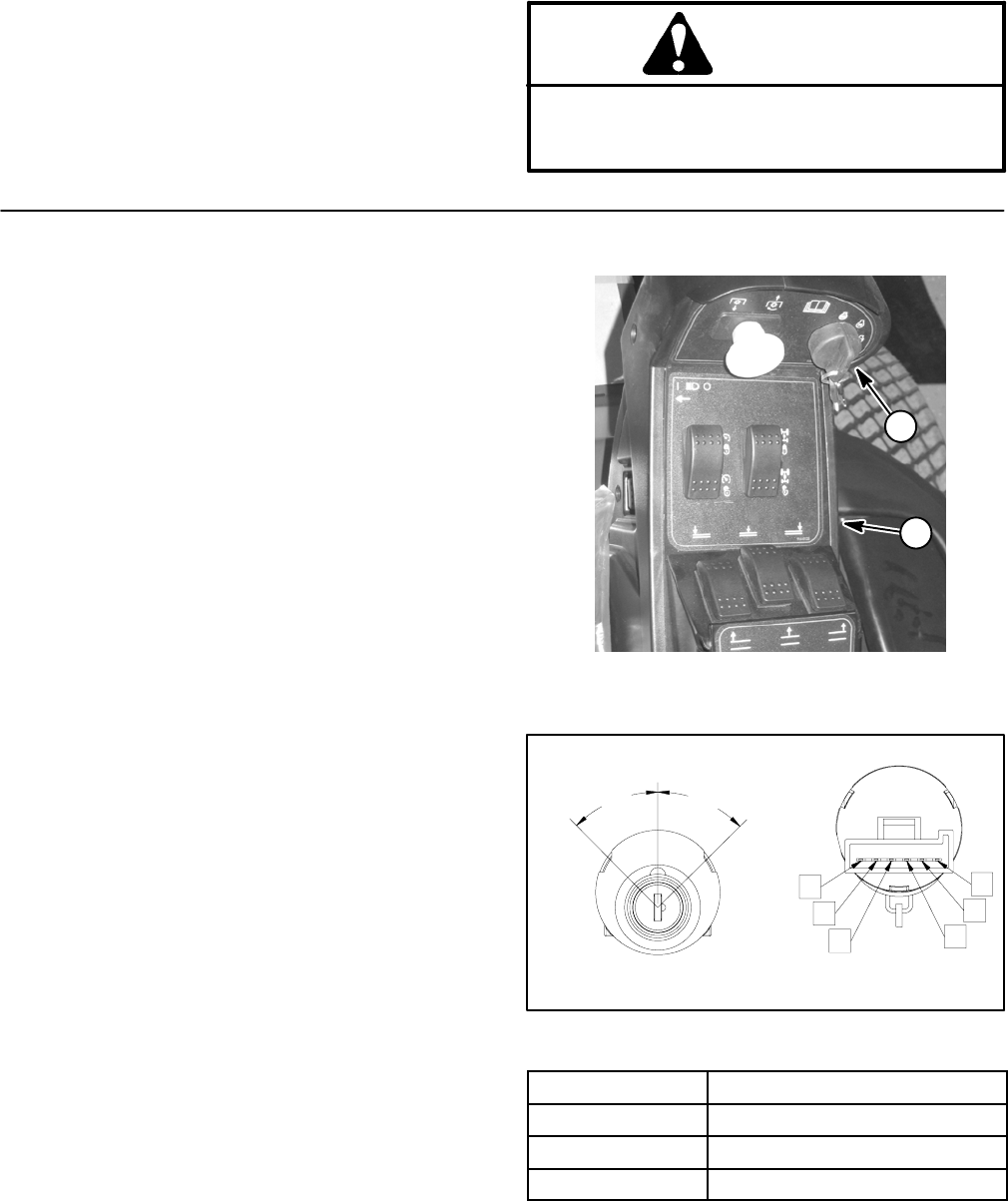
Ignition Switch
The ignition (key) switch has three positions (OFF, RUN
and START). The ignition switch is located on the con-
sole arm (Fig. 55).
Testing
1. Before disconnecting the ignition switch for testing,
the switch and its circuit wiring should be tested as a
TEC c ontroller input with theInfo Center DiagnosticDis-
play (see Info Center Display in this section).
2. If the Diagnostic Display verifies that ignition switch
and circuit wiring are functioning correctly, no further
switch testing is necessary.
3. If the Diagnostic Display determines that ignition
switch and circuit wiring are not functioning correctly,
test ignition switch.
4. Make sure ignition switch is OFF. Remove key from
ignition switch.
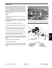
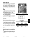
5. Disassemble console arm to gain access to ignition
switch (see Console Arm Disassembly in the Service
and Repairs section of Chapter 7 -- Chassis).
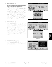
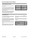
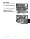
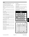
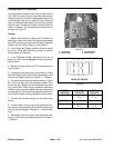
6. The switch terminals are marked as shown in Figure
56. The circuit logic of the ignition switch is shown in the
chart to the right. With theuseofa multimeter (ohms set-
ting), the switch functions may be tested to determine
whether continuity exists between the various terminals
foreachposition.Verifycontinuity betweenswitchtermi-
nals. Replace switch if testing identifies a faulty switch.
7. Connect the wire harness connector to the switch af-
ter testing.
8. If switch tests correctly and circuit problem still ex-
ists, check wire harness (see Electrical Schematics and
Wire Harness Drawings in Chapter 10 -- Foldout Draw-
ings).
9. Assemble console arm cover (see Console Arm As-
sembly in the Service and Repairs section of Chapter 7
-- Chassis).
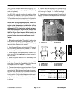
1. Console arm 2. Ignition switch
Figure 55
1
2
Figure 56
REAR VIEW
FRONT VIEW
A
B
C
D
E
F
START
OFF
RUN
45
o
45
o
POSITION CIRCUIT
OFF NONE
RUN B+C+F, D+E
START A+B+C