


Groundsmaster 5900/5910 Hydraulic SystemPage 4 -- 123
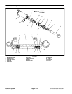
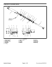
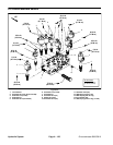
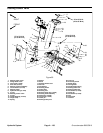
Disassembly (Fig. 89)
1. Remove oil from lift cylinder by slowly pumping the
cylinder shaft. After removingoil from cylinder, plug both
ports and clean the outside of the cylinder.
IMPORTANT: Prevent damage when clamping t he
cylinder’s barrel into a vise; clamp on the barrel cle-
vis only. Do not close vise on barrel.
2. Mount lift cylinder in a vise equipped with soft jaws
by clamping on the barrel clevis.
3. Use a spanner wrench to loosen and remove collar
from barrel.
4. Extract shaft with head, cushion and piston by care-
fully twisting and pulling on the shaft.
IMPORTANT: When securing shaft invise,clamp on
shaft clevisonly.Do not clamp vise jaws against the
shaft surface.
5. Mountshaftsecurelyinavisebyclampingonthecle-
vis of the shaft. Remove lock nut from the shaft. Slide
shaft, cushion and head off the shaft.
6. Remove piston seal, wear ring and O--ring from the
piston. Remove O--ring, back--up ring, dust seal, wear
ring and shaft seal from the head.
7. Wash parts in clean solvent. Dry parts with com-
pressed air. Do not wipe parts dry with paper towels or
cloth. Lint in a hydraulic system will cause damage.
8. Carefully inspect internal surface of barrel for dam-
age (deep scratches, out--of--round, etc.). Replace en-
tire cylinder if barrel is damaged. Inspect shaft and
piston for evidence of excessive scoring, pitting or wear.
Replace any damaged parts.
Assembly (Fig. 89)
1. Make sure all parts are clean before assembly.
2. Coat new O--rings, piston seal, rod seal, back--up
ring, wear rings and dust seal with clean hydraulic oil.
A. Installpistonseal, wear ring and O--ringtothe pis-
ton.
B. Install back--up ring, O--ring, shaft seal, wear ring
and dust seal to the head.
IMPORTANT: When securing shaft invise,clamp on
shaft clevisonly.Do not clamp vise jaws against the
shaft surface.
3. Mount shaft securely in a vise equipped with soft
jaws by clamping on the shaft clevis.
A. Coat shaft with clean hydraulic oil.
B. Slide external collar, head, cushion and piston
onto the shaft.
C. Secure piston to shaft with lock nut. Torque lock
nut to 130 ft--lb (176 N--m).
4. Lubricate head, cushion and piston with clean hy-
draulic oil. Slide shaft assembly carefully into cylinder
barrel.
IMPORTANT: Prevent damage when clamping t he
cylinder’s barrel into a vise; clamp on the barrel cle-
vis only. Do not close vise on barrel.
5. Mount lift cylinder in a vise equipped with soft jaws
by clamping on the barrel clevis.
6. Use a s panner wrench to tighten collar onto barrel.
Hydraulic
System