


Groundsmaster 5900/5910 Page 3 -- 7 Diesel Engine
Adjustments
Valve Clearance
1. Park machine on a level surface, lower cutting
decks, stop engine, engage parking brake and remove
key from the ignition switch.
2. Raise and support hood.
3. Remove valve c over from engine (see Valve Cover
Removalinthe ServiceandRepairs section ofthischap-
ter).
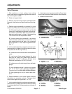
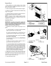
4. Position engine crankshaft so cylinder #1 is at top
dead center (TDC) at the end of the c ompression stroke:
A. While watching the movement of the cylinder #4
intake valve, rotate enginecrankshaftin normal rota-
tion direction (clockwise). When the cylinder #4 in-
take valve starts to open, cylinder #1 is approaching
TDC at the end of the compression stroke.
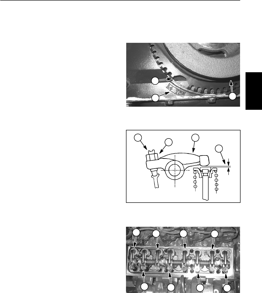
B. Continue rotating the crankshaft in the normal
rotation direction ( clockwise) until the cutout in the
tone wheel attached to the back of the crankshaft
pulleyalignswith“1.4TOP” cast inenginefrontcover
(Fig. 1).
5. In this crankshaft position, adjust valve clearance for
intake valves for cylinders #1 and #3 and exhaust valves
for cylinders #1 and #2 (Fig. 2 and 3).
A. Loosen the lock nuton the rocker armadjustment
screw.
B. Insert correct feeler gauge between the valve
stem and the rocker arm. Intake v alve clearance
specification is 0.014” (0.35 mm). Exhaust valve
clearance specification is 0.020” (0.50 mm).
C. Adjust screw until a slight drag is felt on the feeler
gauge.
D. Hold adjustment screw in position and tighten
lock nut to secure valve clearance adjustment.
Torque lock nut from 29 to 36 ft--lb (39 to 49 N--m).
E. After tightening lock nut, r e--check valve clear-
ance.
6. Rotate crankshaft in the normal rotation direction
(clockwise) one complete revolution. The tone wheel
cutout should again be aligned with “1.4 TOP”.
7. In this crankshaft position, adjust valve clearance for
intake valves for cylinders #2 and #4 and exhaust valves
for cylinders #3 and #4. Follow procedure under step 5
above.
8. Install valve cover to engine (see Valve Cover Instal-
lation in the Service and Repairs section ofthis c hapter).
9. Lower and secure hood.
Figure 1
1. Crankshaft pulley
2. Tone wheel cutout
3. TDC indicator
1
2
3
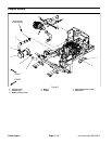
Figure 2
1. Lock nut
2. Adjustment screw
3. Rocker arm
4. Valve clearance
1
2
3
4
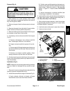
Figure 3
1. #1 intake
2. #1 exhaust
3. #2 intake
4. #2 exhaust
5. #3 intake
6. #3 exhaust
7. #4 intake
8. #4 exhaust
6
1
2
3
4
7
5
8
Diesel
Engine