


Groundsmaster 5900/5910 Hydraulic SystemPage 4 -- 145
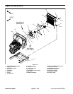
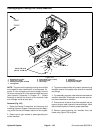
NOTE: The ports on the steering/cooling fan manifold
are marked for easy identification and assembly of com-
ponents. Example: P is the connection port for the sup-
ply from the lift control valve and RV is the relief cartridge
valve port (see Hydraulic Schematic in Chapter 10 --
Foldout Drawings to identifythe function of thehydraulic
lines and cartridge valves at each port).
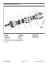
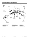
Valve Cartridge Service (Fig. 105)
For cartridge valve service procedures, see Hydraulic
Traction Control Manifold Service in this section. Refer
to Figure 105 for steering/cooling fan manifold cartridge
valve and plug installation torque.
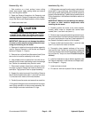
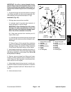
NOTE: The steering/cooling fan control manifold in-
cludes several zero leak NWD plugs. These plugs have
a tapered sealing surface on the plug head that is de-
signed to resist vibration induced plug loosening. The
zero leak plugs also have an O--ring as a secondary
seal. If zero leak plug removal is necessary, lightly rap
the plug head using a punch and hammer before using
an allen wrench to remove the plug: the impact will allow
plug removal with less chance of damage to the socket
head of the plug. When installing plugs, refer to Figure
105 for plug installation torque.
Hydraulic
System