


Groundsmaster 5900/5910Page 5 -- 18Electrical System
Diagnostics
The Info Center DIAGNOSTICS screens allow TEC
controller electrical inputs and outputs to be tested. No
separate code reader or computer is needed to access
the information. Use of the DIAGNOSTICS screens can
be used to identify and troubleshoot machine electrical
functions.
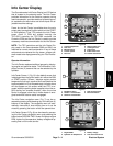
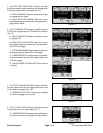
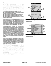
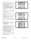
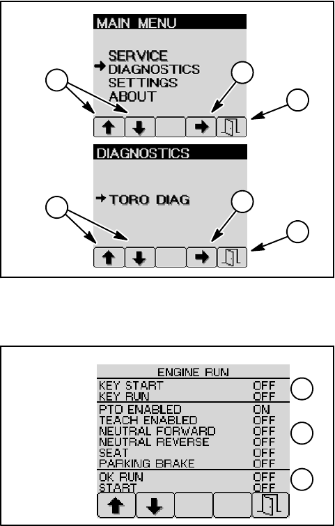
To access the DIAGNOSTICS screen (Fig. 25):
D Go to MAIN MENU screen by pressing and holding
the right button on the Info Center.
D Use navigation arrows to choose DIAGNOSTICS.
D Use navigation arrows to choose TORO DIAG.
D Use navigation arrows to choose machine function
that is to be evaluated.
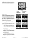
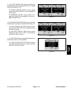
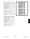
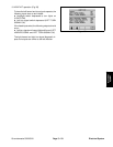
Each DIAGNOSTICS screen is separated into three (3)
areas of information (Fig. 26). The top section identifies
the controller inputs that are necessary for the function
that is being evaluated. The middle section identifies
additional inputs that are involved with the chosen func-
tion. The bottom section identifies the TEC outputs.
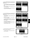
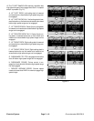
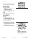
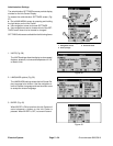
For troubleshooting purposes, the DIAGNOSTICS
screens can be used to identify whether a switch and it’s
circuit wiring are functioning correctly. As an example,
if the ENGINE RUN diagnostic screen is displayed and
the key switch is in the RUN position ( ON), the PTO
switch can be engaged and disengaged while the
screen is viewed. The PTO ENABLED item should indi-
cate the change in status of the PTO switch. If there is
no change on the screen when the switch changes
state, a switch or circuit wiring problem should be inves-
tigated.
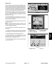
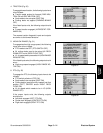
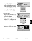
When the correct inputs are received by the TEC con-
trollers, the outputs identified on the DIAGNOSTICS
screen should show as ON. If the inputs are properly
positioned and the output remains OFF, a problem with
TEC controller power (circuit wiring or fuse) or the con-
troller itself should be suspected.
It should be noted that a faulty output component may
not be identified by the DIAGNOSTICS screen. As an
example, if the starter solenoid is faulty, the ENGINE
RUN screen could show that all inputs and outputs are
correct for the function selected. The controller output
occurs but the faulty solenoid w ill prevent the engine
from starting.
DIAGNOSTICS screens are available for the functions
listed on the following pages.
Figure 25
1. Navigation arrows
2. Enter (accept)
3. Exit from menu
2
3
1
1
3
2
Figure 26
TOP
MIDDLE
BOTTOM
1
2
3
1. Function inputs
2. Additional inputs
3. Outputs