


Groundsmaster 5900/5910 Hydraulic SystemPage 4 -- 105
The control manifolds for the three cutting deck sections
are very s imilar. Note: When servicing the PTO control
manifolds, DO NOT interchange parts from one control
manifold to another.
NOTE: The ports on the PTO control manifolds are
marked for easy identification ofcomponents. Example:
Sisthesolenoid valve and M2 is the return from thedeck
motor (see Hydraulic Schematic in Chapter 10 -- Foldout
Drawings to identify the function of the hydraulic lines
and cartridge valves at each port).
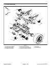
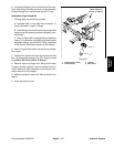
Removal (Fig. 77)
1. Read the General Precautions for Removing and
Installing Hydraulic System Components at the begin-
ning of the Service and Repairs section of this chapter.
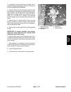
2. To preventcontamination ofhydraulic system during
manifold removal, thoroughly clean exterior of manifold
and fittings.
3. Disconnect wire harness connector from the man-
ifold solenoid valve.
4. Disconnect hydraulic lines from manifold and put
caps or plugs on open hydraulic lines and fittings. Label
disconnected hydraulic lines for proper assembly.
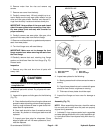
5. Support PTO control manifold to prevent it from fal-
ling.
6. Remove two (2) cap screws and flange nuts that se-
cure manifold to frame. Remove PTO control manifold
from the frame.
7. If hydraulic fittings are to be removed from manifold,
mark fitting orientation to allow correct assembly. Re-
move fittings from manifold and discard O--rings.
Installation (Fig. 77)
1. If fittings were removed from manifold:
A. Lubricate new O--rings with clean hydraulic oil.
Install lubricated O--rings on fittings.
B. Install fittings into manifoldopenings using marks
made during the removal process to properly orien-
tate fittings.
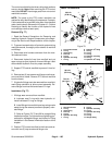
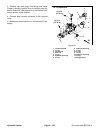
C. Refer to Figures 78, 79 and 80 for straight fitting
installation torque. Forinformation on tightening pro-
cedures for adjustable fittings, see Hydraulic Fitting
Installation in the General Information section of this
chapter.
2. Position PTO control manifold to the frame and se-
cure with two (2) cap screws and flange nuts.
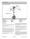
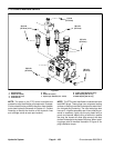
1. Front PTO manifold
2. O--ring
3. Quick fitting
4. Dust cap
5. O--ring
6. Hydraulic 45
o
fitting
7. O--ring
8. Hydraulic 45
o
fitting
9. O--ring
10. O--ring
11. O--ring
12. Hydraulic tee fitting
13. O--ring
14. Hydraulic 90
o
fitting
Figure 78
6
14
10
8
2
3
1
11
9
7
12
13
4
5
5
7
7
20 ft--lb
(27 N--m)
UP
FRONT PTO MANIFOLD
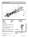
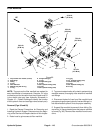
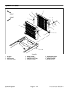
1. RH PTO manifold
2. O--ring
3. Quick fitting
4. Dust cap
5. O--ring
6. Hydraulic 90
o
fitting
7. O--ring
8. O--ring
9. Hydraulic tee fitting
10. O--ring
11. Hydraulic 90
o
fitting
12. O--ring
13. O--ring
14. Straight fitting
Figure 79
6
10
8
2
3
1
11
9
7
12
13
4
5
5
7
8
14
20 ft--lb
(27 N--m)
75 ft--lb
(101 N--m)
UP
RH PTO MANIFOLD
Hydraulic
System