


Groundsmaster 5900/5910 Hydraulic SystemPage 4 -- 137
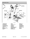
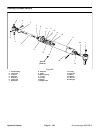
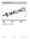
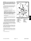
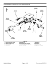
Disassembly (Fig. 99)
1. Removeoil from steering cylinder byslowly pumping
the piston rod. After removingoil fromcylinder, plug both
ports and thoroughly clean the outside of the cylinder.
2. Remove snap ring (item 5) that secures head in bar-
rel.
3. Grasp end of piston rod and use a twisting and pull-
ing motion to carefully extract piston, piston rod and
head from cylinder barrel.
4. Using a wrench on the piston rod flats to prevent the
rod from turning, remove locknut (item 16) from rod.Re-
move piston and head from rod.
5. Remove all seals and O--rings from head and piston.
6. Wash parts in clean solvent. Dry parts with com-
pressed air. Do not wipe parts dry with paper towels or
cloth. Lint in a hydraulic system will cause damage.
7. Carefully inspect internal surface of barrel for dam-
age (deep scratches, out--of--round, etc.). Replace en-
tire cylinder if barrel is damaged. Inspect piston rod and
piston for evidence of excessive scoring, pitting or wear.
Replace any damaged parts.
8. If piston rod ball joint (item 4) removal is necessary,
loosen cap screw (item 2) and lock nut (item 3) and then
unscrew ball joint from piston rod.
9. If necessary, remove barrel end ball joint (item 20)
from barrel as follows:
A. Loosen jam nut (item 19).
B. Drive roll pin (item 18) from barrel.
C. Unscrew ball joint from barrel.
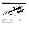
Assembly (Fig. 99)
1. Use a complete repair kit when rebuilding the cylin-
der. Put a coating of clean hydraulic oil on all new seals
and O--rings.
2. Install new O--rings and slipperseal to the piston and
new O--ring, back--up ring, rod seal and rod wiper to
head.
3. Lubricate shaft with c lean hydraulic oil. Slide head
and piston onto piston rod.
4. Using a wrench on the piston rod flats to prevent the
rod from turning, install and tighten lock nut (item 16).
Torque lock nut to 40 ft--lb (54 N--m).
5. Put a coating of clean hydraulic oil on all cylinder
parts to ease assembly.
6. Carefully slide piston rod assembly into cylinder bar-
rel taking care to not damage seals or O--rings.
7. Secure head in barrel with snap ring. Make sure that
snap ring is fully seated in groove in barrel.
8. If barrel end ball joint (item 20) was removed, install
ball joint to barrel as follows:
A. Thread ball joint into barrel so that roll pin hole in
joint aligns with hole in barrel.
B. Drive roll pin into aligned holes in barrel and ball
joint.
C. Tighten jam nut.
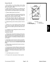
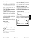
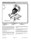
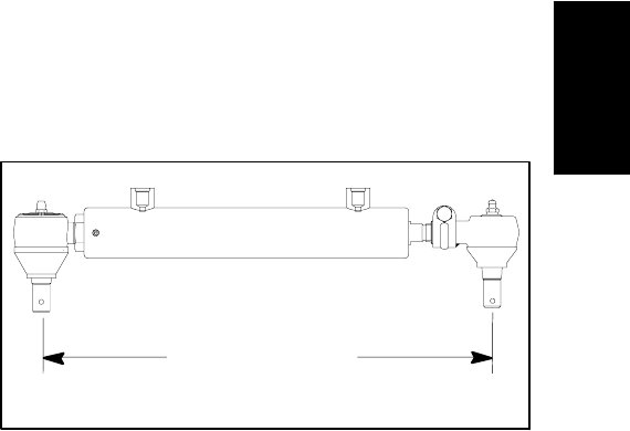
9. If piston rod end ball joint (item 4) was removed, fully
retract piston rod and thread ball joint onto rod so that
center to center length is from 14.270” to 14.330” (362.5
to 363.9 mm) (Fig. 100). Tighten cap screw (item 2) and
lock nut (item 3).
Figure 100
14.270” to 14.330”
(362.5 to 363.9 mm)
Hydraulic
System