


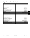

Groundsmaster 5900/5910 Page 3 -- 9 Diesel Engine
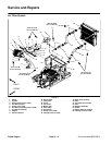
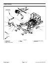
Removal (Fig. 4)
1. Park machine on a level surface, lower cutting
decks, stop engine, engage parking brake and remove
key from the ignition switch.
2. Raise and support hood to allow access to engine.
3. Remove air c leaner components as needed using
Figure 4 as a guide.
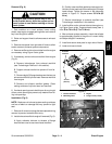
4. Inspect all tubes and clamps for evidence of wear or
damage. Replace components as needed.
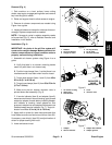
NOTE: If charge air cooler in radiator assembly needs
to be serviced (Fig. 5), refer to Radiator Removal and
Installation in this section.
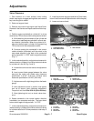
Installation (Fig. 4)
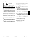
IMPORTANT: Any leaks in the air filter system will
cause serious engine damage. Make sure that all air
cleaner components are in good condition and are
properly secured during installation.
1. Assemble air cleaner system using Figure 4 as a
guide.
A. Verify that tabs in air cleaner mounting bands
mesh fully with slots in air cleaner body.
B. Position hose clamps (item 1) so that there is no
interference with hood foam when hood is closed.
C. Torque hose clamps (items 1 and 10) from 45 to
55 in--lb (5.1 to 6.2 N--m).
D. Torque hoseclamps (item 19) from 50 to 70in--lb
(5.7 to 7.9 N--m).
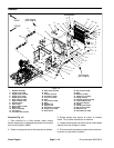
E. Make sure that air cleaner vacuator valve is
pointed down after assembly (Fig. 6).
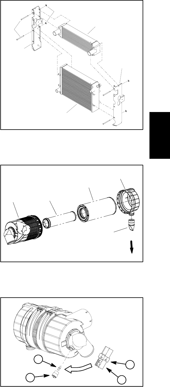
F. If service indicator ( item 8) and adapter (item 9)
wereremovedfromair cleaner housing,applythread
sealant to adapter threads before installing adapter
and indicator to housing. Install adapter so that
groovesinadapterhexandadapterfilterelementare
installed toward service indicator (Fig. 7). Torque in-
dicator from 12 to 15 in--lb (1.4 to 1.6 N--m).
2. Apply chalk on airbox lip, lower hood and check that
hood makes a continuous seal around airbox (item 24).
If necessary, use shim(s) (item 25) to adjust location of
airbox for proper sealing with hood.
3. Lower and secure hood.
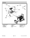
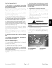
Figure 5
1. Radiator
2. LH cooler bracket
3. Charge air cooler
4. Pin clip (8 used)
5. Pin (8 used)
6. RH cooler bracket
2
1
3
4
6
5
Figure 6
1. Air cleaner housing
2. Safety filter
3. Filter element
4. Cover
5. Vacuator valve
2
1
3
4
5
VACUATOR
DIRECTION
VALVE
Figure 7
1. Adapter
2. Service indicator
3. Adapter filter element
4. Adapter grooves
1
2
3
4
Diesel
Engine