


Groundsmaster 5900/5910Page 3 -- 38Diesel Engine
CAUTION
Make sure thathoist or lift usedto remove engine
can properly support engine. Engine weighs
approximately 606 pounds (275 kg).
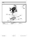
13.Connect suitable hoist or lift to the front and rear lift
tabs on engine.
14.Remove lock nuts, snubbing washers and cap
screws securing the engine brackets to the engine isola-
tor mounts.
CAUTION
One person should operate lift or hoist while the
other person guides the engine out of the ma-
chine.
IMPORTANT: Make sure to not damage the engine,
fuel lines, hydraulic lines, electrical harness or oth-
er machine componentswhile removing theengine.
15.Carefully raise engine from the machine.
16.If necessary, remove engine mount brackets from
the engine.
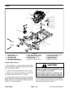
17.If necessary, removeengine isolator mounts (item 8)
from frame. Note that one of the fasteners for the RH
front motor mount also secures the frame ground cable.
18.Cover or plug allengineopeningstopreventcontam-
inants from entering engine.
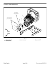
Engine Installation (Fig. 31)
1. If removed, install engine mount brackets to engine
and isolator mounts to frame.
2. Make sure that all parts removed from the engine
during maintenance or rebuilding are correctly installed
to the engine.
3. Remove all covers and plugs from engine openings
that were placed during engine removal.
CAUTION
Make sure that hoist or lift used to install engine
can properly support engine. Engine weighs
approximately 606 pounds (275 kg).
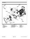
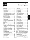
Figure 35
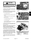
1. AC compressor 2. Connector
1
2
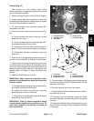
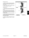
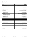
Figure 36
1. Water separator
2. Outlet
3. Fuel hose
1
3
2
4. Connect suitable hoist or lift to the front and rear lift
tabs on engine.
CAUTION
One person should operate lift or hoist while the
other person guides the engineinto themachine.
IMPORTANT: Make sure not to damage the engine,
fuel and hydraulic lines, electrical harness or other
parts while installing the engine.
5. Slowly lower engine into the machine.
6. Align engine mount brackets to the engine isolator
mounts and secure with cap screws, snubbing washers
and lock nuts.
7. Connectfuel hose to waterseparator outlet (Fig. 36).
8. Install hydraulic pump assembly to engine (see
Pump Assembly Installation in the Service and Repairs
section of Chapter 4 -- Hydraulic Systems).