


Groundsmaster 5900/5910Hydraulic System Page 4 -- 82
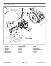
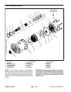
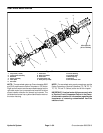
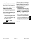
Rear Wheel Motors
1. Rear tire
2. Lug nut (6 used per wheel)
3. Cap screw (4 used per motor)
4. Lock washer (4 used per motor)
5. LH wheel motor
6. Valve stem
7. Tie rod assembly
8. RH steering spindle
9. RH wheel motor
10. Hex nut
11. Square key
12. Wheel stud (6 used per wheel)
13. Wheel hub
14. Hydraulic fitting
15. O--ring
16. O--ring
17. LH steering spindle
18. Wheel rim
19. Steering cylinder (2 used)
20. Rear axle
21. Hydraulic hose
22. Hydraulic hose
Figure 59
FRONT
RIGHT
67 to 83 ft--lb
(91 to 112 N--m)
14
15
20
17
7
5
13
11
9
2
16
4
3
18
12
6
19
10
8
1
70 to 90 ft--lb
(95 to 122 N--m)
315 to 385 ft--lb
(428 to 522 N--m)
21
22
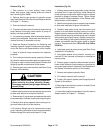
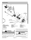
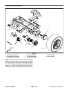
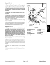
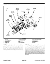
Removal (Fig. 59)
WARNING
Before disconnecting or performing a ny work on
the hydraulic system, all pressure in the system
must be relieved. See Relieving Hydraulic System
Pressure in the General Information section.
1. Park machine on a level surface, lower cutting
decks, stop engine, apply parking brake and remove
key from the ignition switch.
2. Chock front wheels to preventmachinefrom shifting.
3. Loosen,but do not remove,six(6)wheellug nuts and
hex nut (item 10) that secures wheelhubtowheelmotor.
WARNING
Before jacking up the machine, review and f ollow
Jacking Instructions in Chapter 1 -- Safety.
4. Jack up machine enough to allow the removal of the
rear wheel. Support machine with jack stands.