


Groundsmaster 5900/5910Page 5 -- 56Electrical System
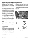
Hydraulic Valve Solenoid Coils
There are numerous hydraulic valve solenoid coils on
the Groundsmasterhydraulic manifolds.Whenthesole-
noid coils are energized, hydraulic valve shift occurs to
control hydraulic flow. Testing of these s olenoid coils
canbedonewith the solenoid coilonthehydraulic valve.
Testing
NOTE: A faulty solenoid coil or solenoid circuit wiring
problem will not be identified by the Info Center Display.
The Info CenterDisplay can be used to verify that output
current from the TEC is availableforthesolenoid coil but
the Display will not verify thatthe solenoid coil and circuit
wiring is functioning correctly.
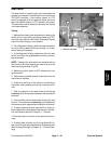
1. Identify the solenoid coil that is to be tested.
2. Disconnect wire harness electrical c onnector from
hydraulic solenoid valve coil that is to be tested.
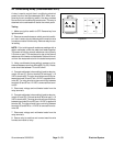
NOTE: Prior to taking small resistance readings with a
digital multimeter, short the meter test leads together.
The meter maydisplay a smallresistance value (usually
0.5 ohms or less). This resistance is due to the internal
resistance of the meter and test leads. Subtract this val-
ue from from the measured value of the component you
are testing.
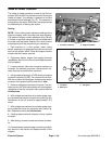
3. Using a multimeter (ohms setting), measure resis-
tance between the two (2) connector terminals on the
solenoid coil. The resistance for the solenoid coils is
identified below:
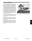
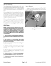
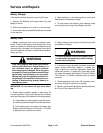
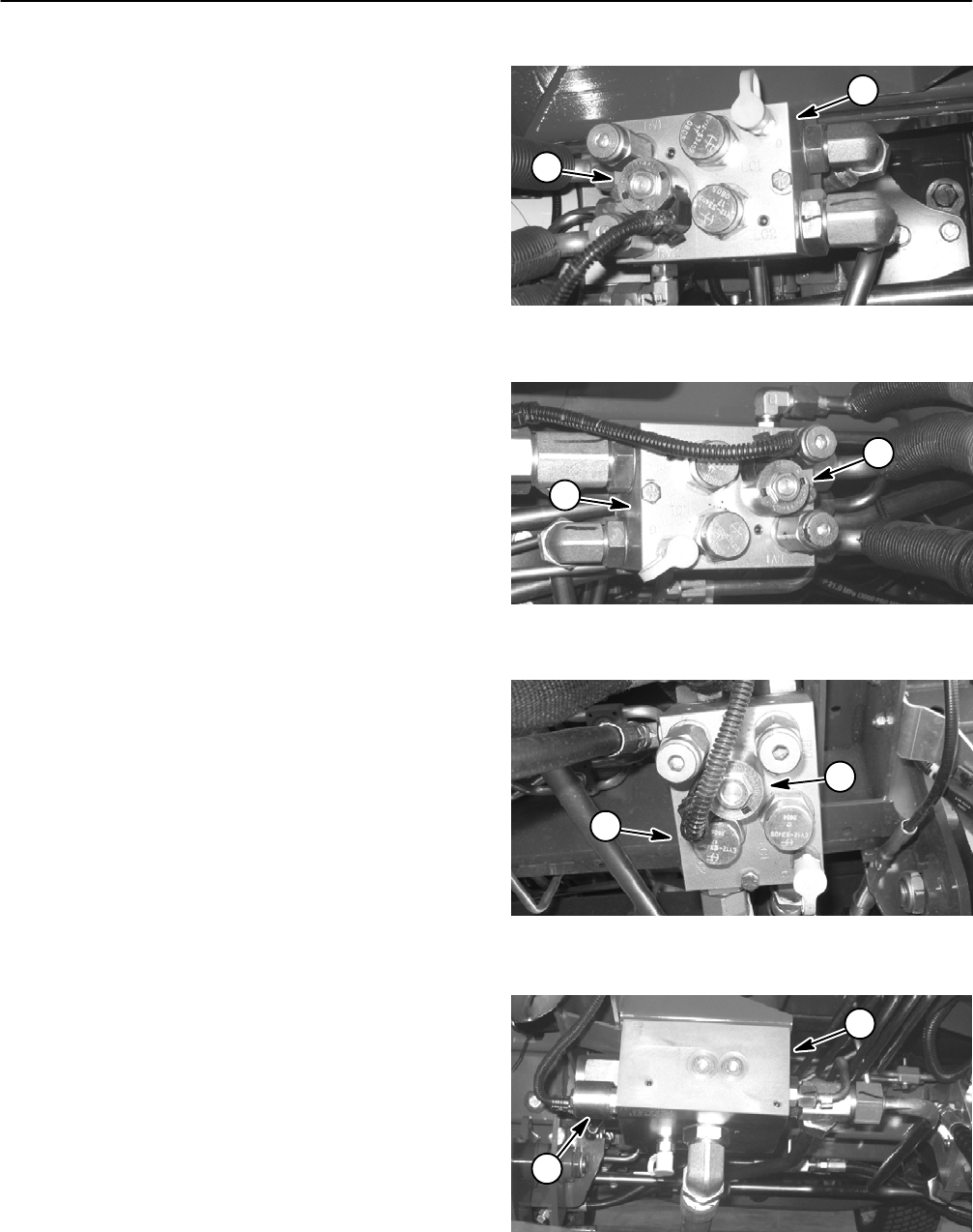
A. The solenoid coils at the following control man-
ifold ports are the same. Resistance of these coils
should be approximately 8.8 ohms.
PTO manifold port S (Figs. 98, 99 and 100)
Traction manifold port S (Fig. 101)
4WD manifold port SV (Fig. 102)
Lift manifold ports S1, S4, S5 and S9 (Fig. 103)
B. The solenoid coils at the following control man-
ifold ports are the same. Resistance of these coils
should be approximately 7.1 ohms.
Lift manifold ports S2, S3, S6, S7 and S8 (Fig.
103)
Steering/cooling fan manifold port PRV (Fig. 104)
C. Resistance of the solenoid coil at steering/cool-
ing fan manifold port S should be approximately 4.6
ohms (Fig. 104).
4. If solenoid coil resistance is incorrect, replace coil
(see Hydraulic Valve Solenoid Coil Removal and Instal-
lation in the Service and Repairs section ofthis c hapter).
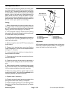
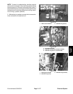
1. LH PTO manifold 2. Solenoid coil (port S)
Figure 98
1
2
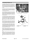
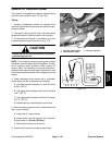
1. RH PTO manifold 2. Solenoid coil (port S)
Figure 99
2
1
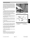
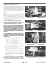
1. Center PTO manifold 2. Solenoid coil (port S)
Figure 100
2
1
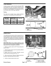
1. Traction control manifold 2. Solenoid coil (port S)
Figure 101
1
2