


Groundsmaster 5900/5910 Page 5 -- 43 Electrical System
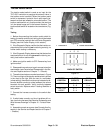
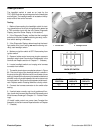
Hi--Lo Speed Switch
The hi--lo speed switch is used as an input for the
TEC--5001 controller to set the machine traction speed
for high speed range (transport) or low speed range
(mow). To change speed range settings with the speed
switch, the machine must be stopped or moving very
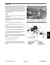
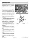
slowly.The hi--lo speed switch is located on the steering
tower (Fig. 77).
Testing
1. Before disconnecting the mow/transport switch for
testing, the switch and its circuit wiring should be tested
as a TEC controller inputwith the Info Center Diagnostic
Display (see Info Center Display in this section).
2. If the Diagnostic Display verifies that the mow/trans-
port switch and circuit wiring are functioning correctly,
no further switch testing is necessary.
3. If the Diagnostic Display determines that the mow/
transport s witch and circuit wiring are not functioning
correctly, test mow/transport switch.
4. Make sure ignition switch is OFF. Remove key from
ignition switch.
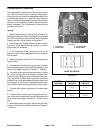
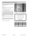
5. Remove front steering tower cover (see Steering
Tower Disassembly in the Service and Repairs section
of Chapter 7 -- Chassis). Locate mow/transport switch
and unplug wire harness connector from s witch.
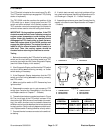
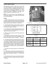
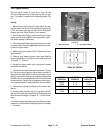
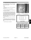
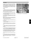
6. The switch terminals are marked as shown in Figure
78. The circuit logic of the mow/transport switch is
shown in the charttothe right. With theuse of a multime-
ter (ohms setting), the switch functions may be tested to
determine whether continuity exists between the vari-
ous terminals for each position. Verify continuity be-
tween switch terminals. Replace switch if testing
identifies a faulty switch.
7. Connect the harness connector to the switch after
testing.
8. If switch tests correctly and circuit problem still ex-
ists, check wire harness (see Electrical Schematics and
Wire Harness Drawings in Chapter 10 -- Foldout Draw-
ings).
9. Installfrontsteering tower cover (see SteeringTower
Assembly inthe Service and Repairs section of Chapter
7 -- Chassis).
1. Steering tower 2. Hi--Lo speed switch
Figure 77
1
2
Figure 78
12
4
3
56
BACK OF SWITCH
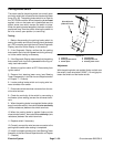
SWITCH
POSITION
CLOSED
CIRCUITS
OPEN
CIRCUITS
MOW
SPEED
2+3
5+6
2+1
5+4
NEUTRAL NONE ALL
TRANSPORT
SPEED
2+1
5+4
2+3
5+6
Electrical
System