


Groundsmaster 5900/5910 Page 7 -- 5 Chassis
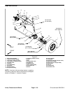
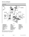
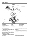
Removal (Fig. 2)
1. Park machine on a level surface, lower cutting
decks, stop engine, apply parking brake and remove
key from the ignition switch.
2. Remove cap screw (item 6) and lock nut (item 5) that
secures rod end of rear impact arm to cutting deck con-
nection. Locate and remove spacer (item 29) from each
side of rod end.
3. Remove lock nut(item 15) and lock washer (item 16)
that secures rear impact arm pivot shaft (item 12). Slide
pivot s haft from pivot hub and impact arm clevis. Re-
move rear impact arm assembly from machine.
Disassembly (Fig. 2)
1. Disassemble wing deck rear impact arm assembly
using Figure 2 as a guide.
2. Thoroughly clean rear impact arm components and
inspect for worn parts. Replace componentsas needed.
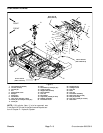
Assembly (Fig. 2)
1. Slide plain washer (item 21), compression spring
(item 23), second plain washer(item 21), plastic bearing
(item 22), third plain washer (item 21) and then flat
washer (item 20) onto spring shaft. Thread one jam nut
(item 19) onto shaft and tighten so that spring length is
12.000” (304.8 mm).
2. Slide the housing (item 26) onto rod end of as-
sembled spring shaft.
3. Insert assembly into rear impact arm housing (item
17).
4. Temporarily secure housing (item 26) to rear impact
arm housing with two (2) cap screws (item 3) and lock
nuts (item 18).
IMPORTANT: All endplay must be removed from
spring shaft assembly to allow proper operation
and ensure long life.
5. Grasp end of spring shaft. Push inward and pull out-
ward on shaft to determine if endplay exists in spring
shaft assembly.
6. If endplay in spring shaft assembly exists, insert a
3/4” socket onto jam nut (item 19) on spring shaft. Ac-
cess to jam nut can be obtained through the open end
of rear impact arm housing. Loosen jam nut until all end-
play in shaft is removed.
7. When no endplayexists in spring shaft assembly, re-
move two (2) cap screws and nuts securing housing
(item 26) to rear impact arm housing. Remove spring
shaft assembly from housing.
8. Thread second jam nut (item 19) onto end of spring
shaft. While holding first jam nut with a wrench to pre-
vent it from turning, torque second jam nut from 135 to
165 ft--lb (184 to 223 N--m) to secure spring adjust-
ment.
9. Thoroughly pack spring with grease. Apply approxi-
mately 40 oz (1.1 kg) of grease to a clean spring.
10.Install spring shaft assembly into rear impact arm
housing and secure housing ( item 26) with four (4) cap
screws (item 3) and lock nuts (item 18).
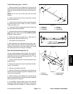
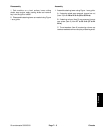
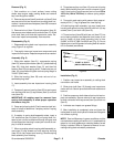
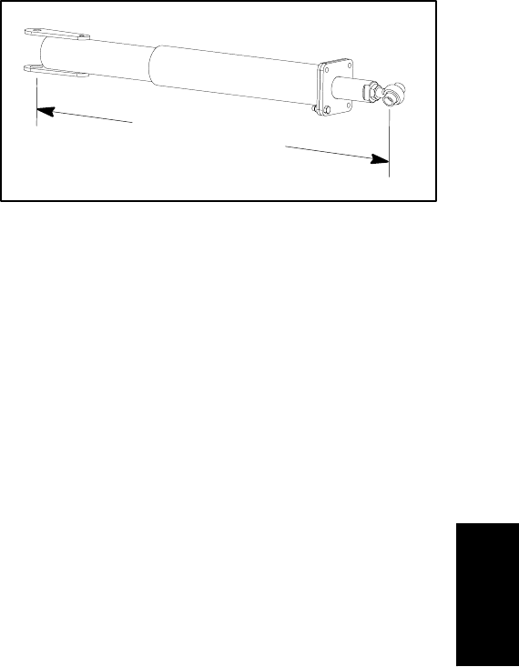
11.Thread rod end (item 28) with jam nut (item 27) into
end of spring shaft so that distance from center of rod
end to center of pivot shaft mounting hole is from
34.890” to 35.010” (886.3 to 889.2 mm) (Fig. 3). Do not
tighten jam nut until alignment of cutting deck to traction
unit is checked (see below).
Figure 3
34.890” to 35.010”
(886.3 to 889.2 mm)
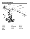
Installation (Fig. 2)
1. Position rear impact arm assembly to cutting deck
connection and frame.
2. Slide pivot shaft (item 12) through rear impact arm
clevis and hub. Secure pivot shaft with lock washer and
lock nut.
3. Position spacers on both sides of rod end of rear im-
pact arm assembly. Secure rod end of rear impact arm
to deck connection with cap screw (item 6) and lock nut
(item 5).
4. Lubricate rear impact arm grease fittings.
5. After installation is completed, raise and lower the
cutting deck to verify that hydraulic hoses and fittings do
not contact anything.
NOTE: Due to differences in grass conditions and the
counterbalance setting of traction unit, it is advised that
grass be cut and appearance checked before formal
cutting is started. Refer to Operator’s Manual for cor-
recting cutting deck mismatch procedures.
Chassis