


Groundsmaster 5900/5910 Page 6 -- 13 Axles, Planetaries and Brakes
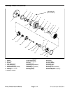
NOTE: Theplanetary wheel drive assemblycanbes er-
vicedwiththeplanetaryinstalledto machine (see Plane-
tary Wheel Drive Service in this section). Use the
following procedure to remove and install planetary
wheel drive assembly from machine.
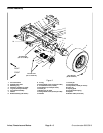
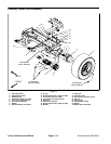
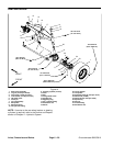
Planetary Wheel Drive Removal (Fig. 9)
1. Park machine on a level surface, lower cutting
decks, stop engine and remove key from the ignition
switch. Do not apply parking brake.
2. Drain oil from planetarywheeldrive/brake assembly.
3. Chock rear wheels to prevent machine from shifting.
CAUTION
When changing attachments, tires or perform-
ing other service,use correct blocks, hoistsand
jacks to raise and support machine. Make sure
machine is parked on a solid level surface such
as a concrete floor. Prior to raising machine, re-
move any attachments that may interfere with
the safe and proper raising of the machine. Al-
ways chock or block wheels. Use appropriate
jack stands to support the raised machine.If the
machine is not properly supported by jack
stands, the machine may move or fall, which
may result in personal injury.
4. Jack up front of machine (see Jacking Instructions in
Chapter 1 -- Safety). Support machine with appropriate
jack stands.
5. Remove front wheel assembly.
6. Remove hydraulic wheel motor (see Front Wheel
Motor Removal in the Service and Repairs section of
Chapter 4 -- Hydraulic System).
7. Remove brake assembly (see Brake Assembly Re-
moval in this section).
8. Supportplanetaryassembly to prevent it from falling.
Loosen and remove six (6) flange head screws that se-
cure planetary assembly to frame. Remove planetary
assembly from machine.
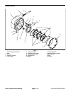
9. Remove and discard gasket (item 7). Make sure that
all gasket material is removedfrom both brake andplan-
etary assemblies.
Planetary Wheel Drive Installation (Fig. 9)
1. Apply Loctite Gasket Sealant #2 (or equivalent) to
sealing surfaces of new gasket (item 7). Apply gasket to
brake assembly.
2. Position planetary assembly to machine frame.
Install six (6) flange head screws that secure planetary
assembly to frame. Torque screws in a crossing pattern
from 75 to 85 ft--lb (101 to 115 N--m).
3. Install brake assembly (see Brake Assembly Instal-
lation in this section).
4. Installhydraulic wheel motor (see Front WheelMotor
Installation in the Service and Repairs section of Chap-
ter 4 -- Hydraulic System).
Failure to maintain proper wheel lug nut torque
could result in failure or loss of wheel and may
result in personal injury.
WARNING
5. Install front wheel assembly.
6. Lower machine from jack stands. Torque wheel lug
nuts in a crossing pattern from 70 to 90 ft--lb (95 to 122
N--m).
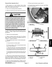
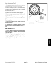
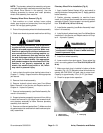
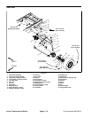
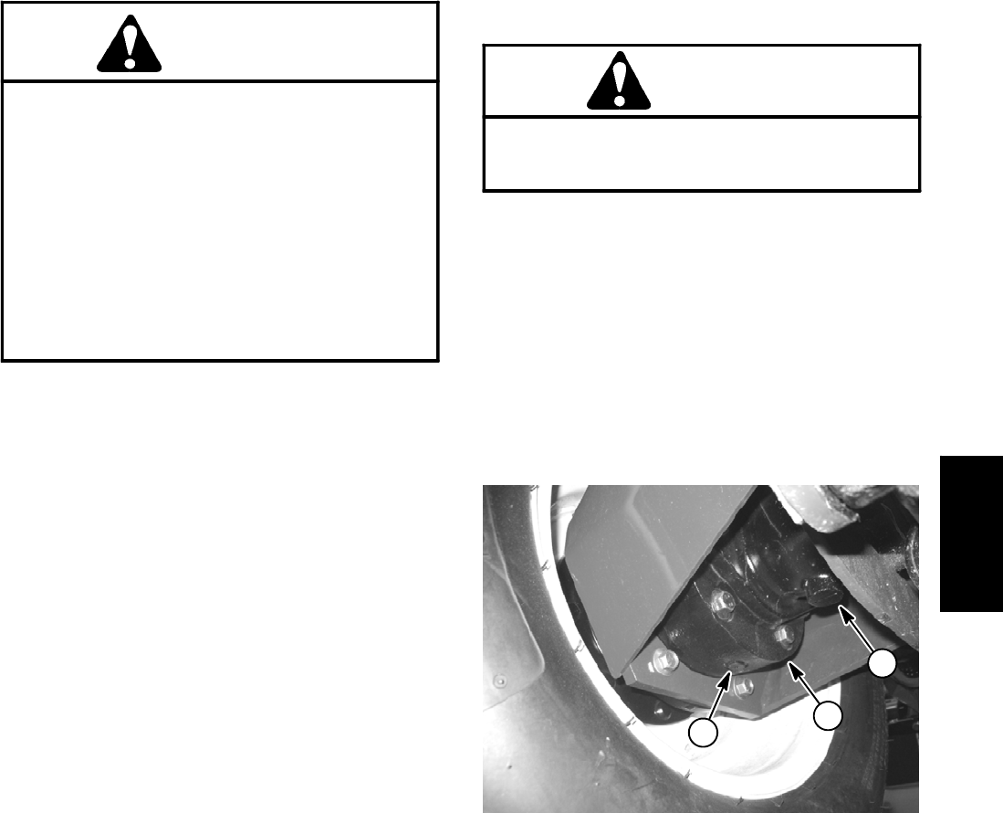
7. Make sure drain plug is installed in bottom of brake
assembly (Fig. 10). Fill planetary wheel drive/brake as-
sembly with SAE 85W--140 gear lube to proper level.
Capacity is approximately 16 oz. (0.47 l) per wheel.
8. Check for proper brake operation.
1. Wheel motor
2. Brake assembly
3. Drain plug
Figure 10
1
2
3
Axles, Planetaries
and Brakes