


Groundsmaster 5900/5910Hydraulic System Page 4 -- 142
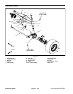
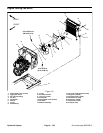
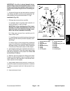
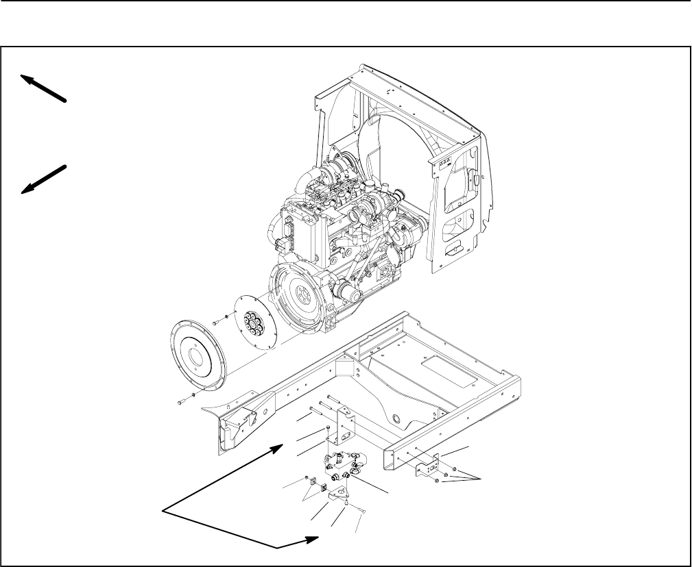
Steering/Engine Cooling Fan Control Manifold
1. Bulkhead mount plate
2. Flange nut (3 used)
3. Steering/cooling fan manifold
4. Carriage bolt
5. Flange head screw (7 used)
6. Tube mount plate
7. Tube clamp
8. Flange nut
9. Manifold mount plate
10. Cap screw (3 used)
Figure 103
FRONT
RIGHT
1
2
6
5
4
3
9
8
7
5
10
106 to 159 in--lb
(12.0 to 17.9 N--m)
NOTE: The ports on the steering/cooling fan manifold
are marked for easy identification of components. Ex-
ample: P is the connection port for the supply from the
lift control valve and RV is the relief cartridge valve port
(see Hydraulic Schematic in Chapter 10 -- Foldout
Drawings to identify the function of the hydraulic lines
and cartridge valves at each port).
Removal (Fig. 103)
1. Read the General Precautions for Removing and
Installing Hydraulic System Components at the begin-
ning of the Service and Repairs section of this chapter.
2. Raise hood to gain access to steering/cooling fan
control manifold.
3. To preventcontamination ofhydraulic system during
manifold removal, thoroughly clean exterior of manifold
and fittings.
4. For assembly purposes, label wire harness leads for
manifold solenoids. Disconnect wire harness connec-
tors from solenoids on manifold.
5. Disconnect all hydraulic lines from manifold and put
caps or plugs on open hydraulic lines and fittings. Label
disconnected hydraulic lines for proper assembly.
6. Remove steering/cooling fan manifold from the
frame using Figure 103 as guide.