


Groundsmaster 5900/5910Hydraulic System Page 4 -- 110
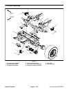
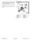
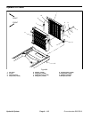
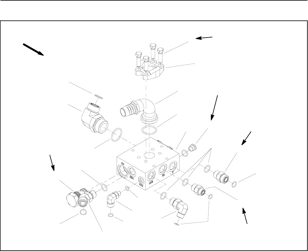
Filter Manifold
1. Cap screw & lock washer (4 used)
2. Split flange
3. Fitting
4. O--ring
5. Filter manifold
6. NWD #6 plug with O--ring
7. O--ring
8. Straight fitting (T)
9. O--ring
10. Straight fitting (T2)
11. O--ring
12. 90
o
hydraulic fitting (CD2)
13. O--ring
14. 90
o
hydraulic fitting (CD3)
15. O--ring
16. 45
o
hydraulic fitting (CD1)
17. Check valve (CV)
18. O--ring
19. 90
o
hydraulic fitting (CL)
20. O--ring
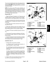
Figure 82
50 ft--lb
(67 N--m)
35 ft--lb
(47 N--m)
6
18
19
20
16
17
14
15
10
8
2
3
1
11
9
7
12
13
4
5
9
7
75 ft--lb
(101 N--m)
75 ft--lb
(101 N--m)
25 ft--lb
(33 N--m)
UP
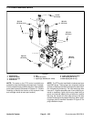
NOTE: The ports on the filter manifold are marked for
easy identification of components. Example: CL is the
connection port for the return from the oil cooler and CV
is the check valve port (see Hydraulic Schematic in
Chapter 10 -- Foldout Drawings to identify the function
of the hydraulic lines and cartridge valves at each port).
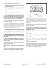
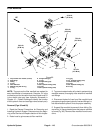
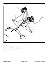
Removal (Figs. 82 and 83)
1. Read the General Precautions for Removing and
Installing Hydraulic System Components at the begin-
ning of the Service and Repairs section of this chapter.
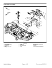
2. Raise hood to gain access to filter manifold.
3. To preventcontamination ofhydraulic system during
manifold removal, thoroughly clean exterior of manifold
and fittings.
4. Disconnect hydraulic lines from filter manifold and
putcapsorplugs on open hydrauliclinesandfittings.La-
bel disconnected hydraulic lines for proper assembly.
5. Support filter manifold to prevent it from falling. Re-
move four (4) flange head screws that secure manifold
to frame (Fig. 83). Remove filter manifold from the ma-
chine.