


Groundsmaster 5900/5910 Page 3 -- 11 Diesel Engine
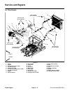
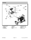
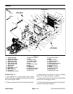
Removal (Fig. 8)
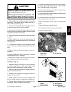
CAUTION
The engine and exhaust system may be hot. To
avoid possible burns, allow the engine and ex-
haust system to cool before working on t he ex-
haust system.
1. Park machine on a level surface, lower cutting
decks, stop engine, engage parking brake and remove
key from the ignition switch.
2. Raise and support hood to allow access to exhaust
system.
3. Remove side panel from right side of frame to allow
easier access to exhaust system components.
4. Removemuffler and/or exhausttubefromtheengine
as necessary using Figure 8 as a guide.
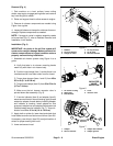
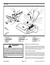
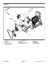
5. If necessary, remove exhaust manifold from engine
(Fig. 9):
A. Remove turbocharger from exhaust manifold
(see Turbocharger Removal in this section).
B. Support exhaust manifold to prevent it from fal-
ling.
C. Remove eight (8) flange head screws that secure
exhaustmanifoldto cylinder head. Remove manifold
from engine.
D. Remove and discard manifold gasket. Clean
mating surfaces of cylinder head and manifold.
6. If exhaust openings are to be left open for any length
of time, cover openings to prevent any material from fal-
ling into openings.
Installation (Fig. 8)
NOTE: Make sure all exhaust system sealing surfaces
are free of debris or damage that may prevent a tight
seal.
1. Removeall covers and plugs that wereplacedduring
removal to prevent contamination entry.
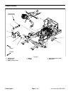
2. Installexhaustmanifold to engine if removed (Fig. 9):
A. Apply antiseize lubricant to threads of flange
head screws used to secure exhaust manifold.
B. Position new manifold gasket and exhaust man-
ifold to cylinder head and secure with eight (8)flange
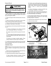
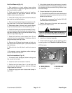
head screws. Tighten the screws in the sequence
shown in Figure 10. Torque screws 33 ft--lb (45
N--m).
C. Secure turbocharger to exhaust manifold (see
Turbocharger Installation in this section).
3. Install muffler and/or exhaust tube to the engine us-
ing Figure 8 as a guide. Torque exhaust clamp (item 1)
from 50 to 70 in--lb (5.7 to 7.9 N--m).
4. After exhaust system assembly, check that tailpipe
is approximately parallel to the ground. Loosen clamp
and adjust tailpipe if necessary.
5. Install and secure side panel to right side of frame.
6. Lower and secure hood.
Figure 9
1. Exhaust manifold
2. Manifold gasket
3. Engine
4. Flange screw (8 used)
2
1
3
4
33 ft--lb
(45 N--m)
Antiseize
lubricant
Figure 10
6
1
2
3
4
7
5
8
Diesel
Engine