


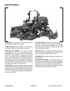

Groundsmaster 5900/5910 Cutting DecksPage 8 -- 9
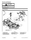
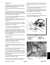
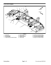
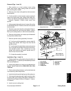
Removal (Fig. 4)
1. Position machine on a clean, level surface. Lower
cutting decks, stop engine, apply parking brake and re-
move key from the ignition switch.
2. Removecutting deckoutercovertoaccess hydraulic
deck motor.
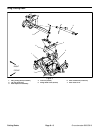
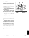
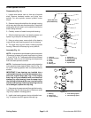
3. Remove three (3) hose guides from cutting deck
(Fig. 5). Leave two (2) loop guides (Fig. 5, item 6) on hy-
draulic hoses.
4. Remove hydraulic motor from cutting deck (see Cut-
ting Deck Motor Removal in the Service and Repairs
Section of Chapter 4 -- Hydraulic Systems). Position and
support motor away from cutting deck.
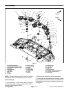
5. Remove eight (8) flange head screws (item 5) and
lock nuts (item 4) that secure deck connection (item 6)
to cutting deck.
6. Raise lift arm enough to separate deck connection
from cutting deck.
7. Slide the cutting deck away from the traction unit.
Installation (Fig. 4)
1. Position machine on a clean, level surface. Lower
wing deck lift arm, stop engine, engage parking brake
and remove key from the ignition switch.
2. Position the wing cutting deck to the raised lift arm.
3. Lower lift arm while aligning deck connection to cut-
ting deck.
4. Install deck connection to cutting deck with eight (8)
flangeheadscrews(item5)andlock nuts(item 4). Tight-
en fasteners.
5. Install hydraulic motor to cutting deck (see Cutting
Deck Motor Installation in the Service and Repairs Sec-
tion of Chapter 4 -- Hydraulic Systems).
6. Position and secure three (3) hose guides to cutting
deck (Fig. 5).
7. Install all removed cutting deck covers.
8. Lubricate grease fittings on cutting deck and lift arm
assemblies (see Operator’s Manual).
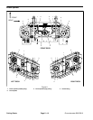
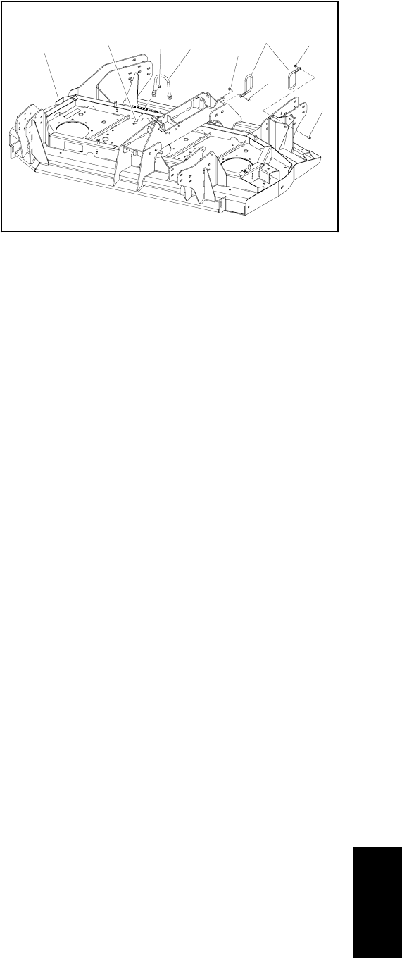
1. Wing deck (RH shown)
2. Carriage screw (2 used)
3. Flange nut (2 used)
4. Hose guide
5. Flange nut (4 used)
6. Hose guide
7. Cap screw (4 used)
Figure 5
3
4
5
6
1
2
7
7
5
Cutting Decks