


Groundsmaster 5900/5910 Hydraulic SystemPage 4 -- 135
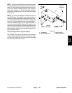
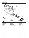
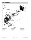
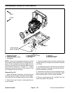
Removal (Fig. 98)
1. Park machine on a level surface, lower cutting
decks, stop engine, apply parking brake and remove
key from the ignition switch.
2. Read the General Precautions for Removing and
Installing Hydraulic System Components at the begin-
ning of the Service and Repairs section of this chapter.
3. To preventcontamination ofhydraulic system during
steering cylinder removal, thoroughly clean exterior of
cylinder, fittings and hoses.
NOTE: To ease assembly, label all hydraulic hoses to
identify their correct position on the steering cylinder.
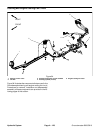
4. Disconnect hydraulic hoses from steering cylinder
fittings. Put caps or plugs on fittings and hoses to pre-
vent contamination. Tag hydraulic lines for proper as-
sembly.
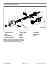
5. Removecotter pinsand slotted hex nuts (items 1 and
8) that secure the cylinder ball joints to rear axle and
steering spindle.
6. Separate ball joints from rear axle and steering
spindle. Remove steering cylinder from machine.
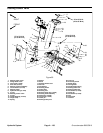
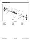
7. If hydraulic fittings are to be removed from steering
cylinder, mark fitting orientation to allow c orrect assem-
bly. Remove fittings from steering cylinder and discard
O--rings from fittings.
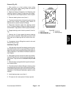
Installation (Fig. 98)
1. If fittings were removed from steering cylinder, lubri-
cate and place new O--rings onto fittings. Install fittings
into cylinder ports usingmarksmade during the removal
process to properly orientate fittings. Tighten fittings
(see Hydraulic Fitting Installation in the General Infor-
mation section of this chapter).
2. Thoroughly clean tapers on steering cylinder ball
joints. Also, clean ball joint bores of rear axle assembly
and steering spindle.
3. Position steering cylinder to machine.
4. Secure steering cylinder to rear axle and steering
spindle with slotted hex nuts (items 1 and 8). Torque
slotted hex nuts from 30 to 45 ft--lbs (41 to 61 N--m)
while aligning ball joint hole with slot in nut. Insert cotter
pins.
5. Remove caps or plugs placed during removal to pre-
vent contamination.
6. Using tags placed during cylinder removal, correctly
attach hydraulic hosesto steering cylinder (see Hydrau-
lic Hose and Tube Installation in the General Information
section of this chapter).
7. Fill reservoir with new hydraulic fluid as required.
8. Lubricate cylinder ball joint grease fittings.
9. After assembly is completed, operate steering cylin-
der to verify that hydraulic hoses and fittings do not con-
tact any machine components.
Hydraulic
System