


Groundsmaster 5900/5910 Page 7 -- 9 Chassis
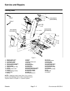
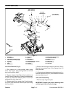
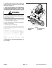
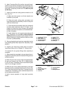
Removal (Fig. 6)
1. Park machine on a level surface, lower cutting
decks, stop engine, apply parking brake and remove
key from the ignition switch.
2. Remove front cutting deck (see Cutting Deck Re-
moval in Chapter 8 -- Cutting Units).
CAUTION
When changing attachments, tires or perform-
ing other service,use correct blocks, hoistsand
jacks to raise and support machine. Make sure
machine is parked on a solid level surface such
as a concrete floor. Prior to raising machine, re-
move any attachments that may interfere with
the safe and proper raising of the machine. Al-
ways chock or block wheels. Use appropriate
jack stands to support the raised machine.If the
machine is not properly supported by jack
stands, the machine may move or fall, which
may result in personal injury.
3. Chock rear wheels and jack up front of machine.
Support machine on jack stands. Remove front wheel
nexttoliftarm that isbeingremoved(seeWheel Remov-
al in the Service and Repairs section of Chapter 6 --
Axles, Planetaries and Brakes).
4. Remove flange head screw and flange nut that se-
cure lift cylinder pin (item 4) to lift arm. Remove pin and
separate lift cylinder from lift arm.
5. Remove lock nut (item 24) that secures lift arm pin
(item 3).
6. Support lift arm and slide pin from frame and lift arm.
Remove lift arm from frame.
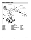
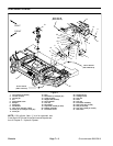
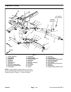
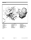
7. As needed, disassemble lift arm (Fig. 7):
A. Remove height--of--cut chain.
B. Remove lock nut, flat washer and support hub
from tapered stud in lift arm.
C. Remove retaining ring that secures spherical
bearing in lift arm. Remove tapered stud with spheri-
cal bearing from lift arm. Separate flange nut and
spherical bearing from stud.
D. Press flange bushings from lift arm. Thoroughly
clean lift arm bore.
1. Lift arm (LH shown)
2. Grease fitting
3. Flange bushing
4. Retaining ring
5. Tapered stud
6. Spherical bearing
7. Jam nut (2 used)
8. Flange nut
9. Carriage screw
10. Trigger sensor
11. Flange nut
12. U--bolt
13. HOC chain
14. Lock nut
15. Support hub
16. Thrust washer
17. Flat washer
18. Lock nut (2 used)
19. Flat washer (4 used)
Figure 7
2
3
1
4
5
6
8
2
3
9
10
11
17
16
15
12
13
14
18
19
19
7
135 to 165 ft--lb
(184 to 223 N--m)
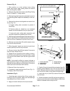
Installation (Fig. 6)
1. If removed, install components to lift arm (Fig. 7):
A. Assemble height--of--cut chain u--bolt so that
threaded portion of u--bolt extends 1.200” (30.5 mm)
above mounting plate on lift arm.
B. Lightly lubricate new flange bushings and press
bushings into lift arm. Make sure that bushing flange
is pressed fully to lift arm surface.
C. Install spherical bearing on tapered stud and se-
cure with flange nut. Install stud with spherical bear-
ing into lift arm and secure with retaining ring.
D. Thoroughly clean tapered surfaces of stud and
mounting boss of support hub. Secure support hub
(position slotted hole in hub toward rear of deck) to
tapered stud with flat washer and lock nut. Tighten
lock nut from 135 to 165 ft--lb (184 to 223 N--m).
2. Position lift arm to frame and insert lift arm pin. En-
gage roll pin into frame slots and install lock nut on pin.
Torque lock nut from 60 to 70 ft--lb (82 to 94 N--m).
Chassis