


Groundsmaster 5900/5910 Page 6 -- 7 Axles, Planetaries and Brakes
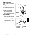
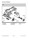
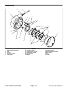
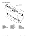
Remove Brake Assembly (Fig. 2)
1. Park machine on a level surface, lower cutting
decks, stop engine and remove key from the ignition
switch. Do not apply parking brake.
2. Drain oil from planetary/brake assembly.
3. Chock rear wheels to prevent machine from shifting.
CAUTION
When changing attachments, tires or perform-
ing other service,use correct blocks, hoistsand
jacks to raise and support machine. Make sure
machine is parked on a solid level surface such
as a concrete floor. Prior to raising machine, re-
move any attachments that may interfere with
the safe and proper raising of the machine. Al-
ways chock or block wheels. Use appropriate
jack stands to support the raised machine.If the
machine is not properly supported by jack
stands, the machine may move or fall, which
may result in personal injury.
4. Jack up front of machine (see Jacking Instructions in
Chapter 1 -- Safety). Support machine with appropriate
jack stands.
5. Remove front wheel assembly.
6. Remove hydraulic wheel motor (see Front Wheel
Motor Removal in the Service and Repairs section of
Chapter 4 -- Hydraulic System).
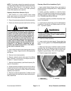
7. Disengage brake lever (item 14) from brake assem-
bly pull rod:
A. Remove tension on brake cable.
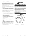
B. Remove cotter pin (item 13) that secures brake
lever to front axle frame.
C. Slide clevis pin (item 17) from axle frame bracket
and brake lever. Remove two (2) washers (item 16)
from between brake lever and frame bracket (Fig. 5).
D. Shiftbrakelevertowardthecenterofthemachine
to disengage lever slot from pull rod on brakeassem-
bly.
8. Remove four (4) flange headscrews (item9) that se-
cure brake assembly to machine. Remove brake as-
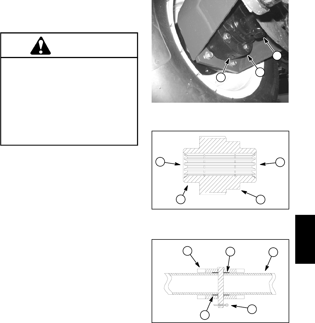
sembly from machine. Take care to not drop splined
brake coupler (item 2) as brake assembly is removed.
9. Remove and discard gasket (item 7). Make sure that
all gasket material is removedfrom both brake andplan-
etary assemblies.
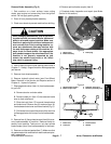
10.Remove splined brake coupler (item 2).
11.Complete brake inspection and repair (see Brake
Service in this section).
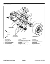
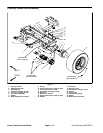
1. Wheel motor
2. Brake assembly
3. Drain plug
Figure 3
1
2
3
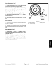
1. Splined brake coupler
2. Brake coupler step
3. Hydraulic motor end
4. Planetary assembly end
Figure 4
2
3
4
1
1. Brake lever
2. Cotter pin
3. Frame bracket
4. Washer
Figure 5
2
1
3
4
4
Axles, Planetaries
and Brakes