


Groundsmaster 5900/5910Hydraulic System Page 4 -- 124
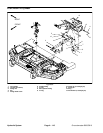
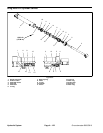
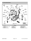
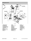
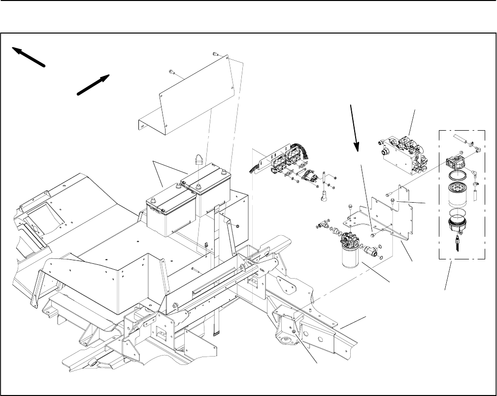
Lift Control Manifold
1. Battery
2. Lift control manifold
3. Water separator assembly
4. Flange head screw (3 used)
5. Flange head screw (4 used)
6. Mounting plate
7. Hydraulic filter
8. Flange nut (3 used)
9. Frame
Figure 90
FRONT
RIGHT
2
1
9
3
7
8
5
6
4
106 to 159 in--lb
(12.0 to 17.9 N--m)
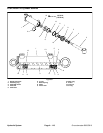
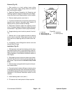
NOTE: Theports on the liftcontrol manifold aremarked
for easy identification of components. Example: P1 is
the supply port from the gear pump and FD is the flow
divider cartridge location (see Hydraulic Schematic in
Chapter 10 -- Foldout Drawings to identify the function
of the hydraulic lines and cartridge valves at each port).
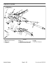
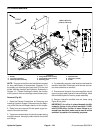
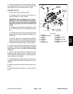
Removal (Fig. 90)
1. Read the General Precautions for Removing and
Installing Hydraulic System Components at the begin-
ning of the Service and Repairs section of this chapter.
2. Raise hood and remove RH side panel to gain ac-
cess to lift control manifold.
3. To preventcontamination ofhydraulic system during
manifold removal, thoroughly clean exterior of manifold
and fittings.
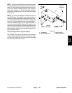
4. For assembly purposes, label wire harness leads for
manifold solenoids. Disconnect wire harness connec-
tors from solenoids on manifold.
5. Disconnect all hydraulic lines from manifold and put
caps or plugs on open hydraulic lines and fittings. Label
disconnected hydraulic lines for proper assembly.
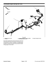
6. Remove hydraulic manifold from the frame using
Figure 90 as guide.
IMPORTANT: An orifice is placed beneath the 90
o
hydraulic fittings in the control manifold C1--OR1
and C5--OR2 ports. If either of these fittings is re-
moved from manifold, make sure to remove orifice
and label its position for assembly purposes.