


Groundsmaster 5900/5910Page 7 -- 14Chassis
6. Apply Permatex Blue Gel medium strength thread-
locker (or equivalent) to threads of cap screw (item 23).
Secure pivot hub topivotshaftwithwasher(item24)and
cap screw. Torque cap screw from 77 to 96 ft--lb (105
to 130 N --m).
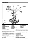
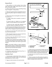
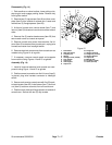
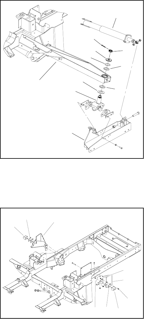
7. Install joint yoke and cutting deck connection to lift
arm (Fig. 12):
A. Make sure that spacer and thrust washer are
installed on joint yoke.
B. Raise joint yoke, cutting deck connection and
wing deck impact arm assemblyto lift arm. Slide joint
yoke into lift arm bore.
C. Place second thrust washer onto joint yoke shaft
and then place washer(s) (item 5 in Figure 12) as
needed to remove as much clearance as possible
between second thrust washer and hardened wash-
er (item 4) location.
D. Install slotted hex nut to secure joint yoke to lift
arm. Torque hex nut from 150 to 180 ft--lb (204 to
244N--m). Make sure thatjointyokerotatesinliftarm
without binding and that excessive clearance does
not exist in y oke assembly.
8. Secure wing deck rear impact arm assembly to pivot
hub (see Wing Deck Rear Impact Arm Assembly in this
section).
9. Position and install wing c utting deck to machine
(see Wing Cutting Unit in Chapter 8 -- Cutting Units).
10.Lubricate lift arm grease fittings after assembly is
complete.
11.After assembly is completed,raise andlower thecut-
ting deck to verify that hydraulichoses andfittingsdonot
contact anything.
12.When lift arm is fully raised, check that gap between
lift arm and bumper pad (item 32) is approximately
0.100” (2.5 mm). If necessary, add or remove shim pads
(item 31) so that gap is correct.
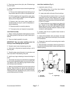
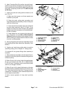
13.When lift arm is fully raised, the bumper on the stop
bracket should be contacted slightly by the lift arm (Fig.
13). There should be less than one (1) bumper shim of
interference. If necessary,add or remove bumpershims
so that slight contact exists.
14.Verify correct operation of wing deck proximity
switch.
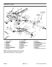
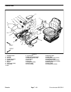
1. Lift arm (LH shown)
2. Joint yoke
3. Deck connection
4. Hardened washer
5. Thrust washer
6. Thrust washer
7. Spacer
8. Rear impact arm
9. Slotted hex nut
10. Cotter pin
Figure 12
2
1
3
4
5
6
7
8
6
9
10
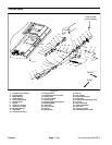
1. Bumper
2. Flange head screw
3. Bumper shim
4. Lock nut
5. LH stop bracket
6. Flange nut
7. RH stop bracket
Figure 13
2
1
3
4
5
1
3
6
7