


Groundsmaster 5900/5910 Page 7 -- 7 Chassis
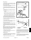
2. Press base mounts from joint yoke. Slide bearings
from joint yoke.
3. Useapresstoremovecrossand remainingbearings
from yoke:
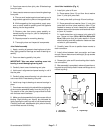
A. Place a small socket against one bearing and a
large socket against the yoke on the opposite side.
B. While supporting the large socket, apply pres-
sure on small socket to partially push the opposite
bearing into the large socket.
C. Remove yoke from press, grasp partially re-
moved bearing and tap on yoke to completely re-
move the bearing.
D. Repeat process for remaining bearing.
E. Thoroughly clean and inspect all components.
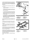
Joint Yoke Assembly
1. Apply a coating of grease to bearing bores of yoke.
Also, apply grease to bearings and seal of bearing as-
sembly.
2. Press one bearing partially into yoke.
IMPORTANT: Take care when installing cross into
bearing to avoid damaging bearing seal.
3. Carefully insert cross into bearing and yoke.
4. Hold cross in alignment and press bearing in until it
hits the yoke.
5. Carefully place second bearing into yoke bore and
onto cross shaft. Press bearing into yoke.
6. Install snap rings to bearings to secure bearings in
place.
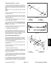
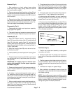
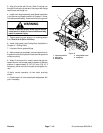
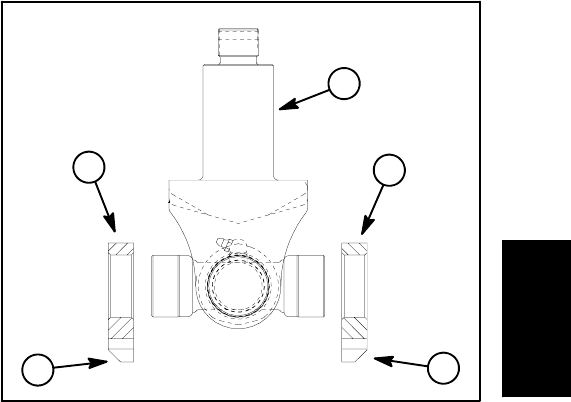
7. Pressbase mounts to jointyokewith the angled edge
of the mounts assembled away from the joint (Fig. 5).
The outside of the yoke bearing cups should be flush
with the base mount surfaces.
8. Make sure that assembled joint yoke moves without
binding. Slight binding can usually be eliminated by
lightly rapping the yoke lugs with a soft faced hammer.
If binding continues, disassemble joint yoke to identify
and eliminate source of binding.
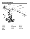
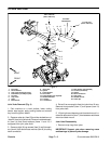
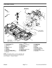
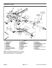
Joint Yoke Installation (Fig. 4)
1. Install joint yoke to lift arm:
A. Place spacer (item 10) and then thrust washer
(item 11) onto joint yoke shaft.
B. Insert yoke shaft up through lift arm bushings.
C. Place second thrust washer (item 11) onto joint
yoke shaft and then place washer(s) (item 13) as
needed to remove as much clearance as possible
between second thrust washer and hardened wash-
er (item 14) location.
D. Install slotted hex nut to secure joint yoke to lift
arm. Torque nut from 150 to 180 ft--lb (204 to 244
N--m). Make sure that joint yoke rotates in lift arm
without binding and that excessive clearance does
not exist in y oke assembly.
2. Carefully lower lift arm to position base mounts to
deck connection.
3. Install shims between deck connection and base
mounts. Secure base mounts with eight (8) cap screws
and flat washers.
4. Grease joint yoke and lift arm bushing after installa-
tion on machine.
5. Afterassemblyis completed, raise and lower the cut-
ting deck to verify that hydraulichoses andfittingsdonot
contact anything.
1. Joint yoke
2. Base mount
3. Angled edge
Figure 5
1
2
2
3
3
Chassis