


Groundsmaster 5900/5910 Page 5 -- 51 Electrical System
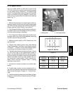
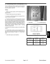
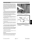
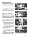
Service Brake Switches
Thetwo(2) switchesusedforthe service brakesarenor-
mally open switches that are located under the footrest
panel (Fig. 90). The service brake switches provide in-
puts for the TEC--5002 controller. When a brake pedal
isnotdepressed,thebrake pedal assembly contactsthe
switch plunger to close the switch. When a brake is ap-
plied, the brake pedal assembly moves away from the
switch plunger, allowing the switch plunger to extend
and the switch to open.
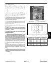
Testing
1. Before disconnecting a service brake switch for test-
ing, the switch and its circuit wiring should be tested as
a TEC controller input with the Info Center Diagnostic
Display (see Info Center Display in this section).
2. If the Diagnostic Display verifies that the service bra-
ke switch and circuit wiring are functioning correctly, no
further switch testing is necessary.
3. If the Diagnostic Display determines that the service
brake switch and circuit w iring are not functioning cor-
rectly, test seat switch.
4. Make sure ignition switch is OFF. Remove key from
ignition switch. Locate service brake switch for testing.
5. Disconnect switch electrical connector from the ma-
chine wire harness.
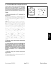
6. Check the continuity of the switch by connecting a
multimeter (ohms setting) across the connector termi-
nals.
7. When the service brakeis not applied (service brake
switch plunger depressed), there should be continuity
(zero resistance) between the switch terminals.
8. When the service brake is applied (service brake
switch plunger extended), there should be no continu-
ity (infinite resistance) between the switch terminals.
9. Replace switch if necessary.
10.Reconnect s witch electrical connector to the ma-
chine wire harness after testing.
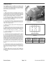
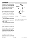
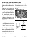
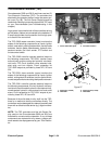
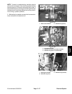
Adjustment
Adjust the service brake switch so that the switch plung-
er always makes full contact with the brake pedal. Tight-
en fasteners from 13 to 17 in--lb (1.5 to 1.9 N--m).
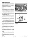
1. Service brake switch 2. Footrest panel
Figure 91
1
2
1
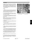
1. Screw (2 per switch)
2. Footrest panel
3. Switch (2 used)
4. Lock nut (2 per switch)
Figure 92
1
3
4
2
13 to 17 in--lb
(1.5 to 1.9 N--m)
Electrical
System