


Groundsmaster 5900/5910 Hydraulic SystemPage 4 -- 67
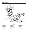
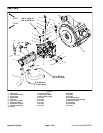
Removal (Fig. 49)
1. Park machine on a level surface, lower cutting
decks, stop engine, apply parking brake and remove
key from the ignition switch.
2. Read the General Precautions for Removing and
Installing Hydraulic System Components at the begin-
ning of the Service and Repairs section of this chapter.
3. To preventcontamination ofhydraulic system during
hydraulic reservoir removal, thoroughly cleanexteriorof
reservoir, fittings and hoses.
4. Remove drain plug and empty r eservoir into a suit-
able container.
5. To allow access to reservoir fasteners, loosen fuel
tank and slide it toward left side of machine (see Fuel
Tank Removal in the Service and Repairs section of
Chapter 3 -- Diesel Engine).
6. To ease assembly, label all hydraulic hoses to identi-
fy their correct position on the reservoir.
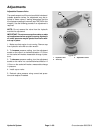
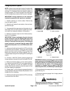
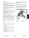
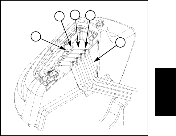
NOTE: Original production clamps used to secure
hoses to stand pipes and hydraulic tubes are crimped
and will need to be cut in order to remove hoses (Fig.
50). Replacement clamps are traditional worm clamps.
7. Disconnect hydraulic hoses from reservoir fittings.
Put caps or plugs on fittings and hoses to prevent con-
tamination.
8. Remove hydraulic reservoir using Figure 49 as a
guide.
Inspection
1. Clean hydraulic reservoir and tank strainer with sol-
vent.
2. Inspect reservoir for leaks, cracks or other damage.
Installation (Fig. 49)
1. Install reservoir using Figure 49 as a guide.
A. Torque drain plug (item 22) from 155 to 171 in--lb
(18to19N--m).
B. Torque tank strainer (item 23) from 105 to 115 ft--
lb (143 to 155 N--m).
2. Remove caps or plugs placed during removal to pre-
vent contamination.
3. Usingtagsplaced during reservoir removal,properly
connect hydraulic hoses to reservoir fittings and secure
with hose clamps.
4. If hose guard (item 33) was removed, install guard
with split orientated up and secure with two (2) cable
ties.
5. Slide fuel tank to proper location on machine and se-
cure in place (see Fuel Tank Installation in the Service
and Repairs section of Chapter 3 -- Diesel Engine).
6. Fill reservoir with new hydraulic fluid.
1. Stand pipe
2. Hose clamp
3. Hose
4. Hydraulic tube
Figure 50
1
4
2
2
3
Hydraulic
System