


Groundsmaster 5900/5910 Cutting DecksPage 8 -- 15
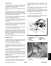
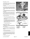
Removal (Figs. 11 and 13)
1. Park machine on a level surface, lower cutting
decks, stop engine, apply parking brake and remove
key from the ignition switch.
2. Remove covers from cutting deck to allow access to
blade spindle.
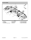
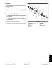
3. If drive spindle is to be serviced, remove hydraulic
motor from cutting deck (see Cutting Deck Motor Re-
moval in the Service and Repairs Section of Chapter 4
-- Hydraulic Systems). Position motor away from
spindle.
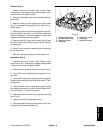
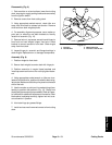
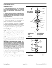
4. Using appropriate socket wrench,loosen idler pulley
to release belt tension. Remove drive belt from spindle
to be serviced.
5. Start the engine and raise the cutting deck. Stop en-
gine and remove key from the ignition switch. Latch or
block up the cutting deck so it cannot fall accidentally.
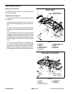
6. Remove cutting blade, anti--scalp cup and blade bolt
from spindle to be serviced.
7. Remove spindle housing assembly from deck.
A. For driven spindle assemblies, remove eight (8)
flange head screws with flange nuts that secure
spindle to deck.
B. Fordrive spindle assemblies, loosen andremove
four (4) flange head screws with flange nuts that se-
cure spindle to deck. Then, remove four (4) cap
screws with washers that secure spindle and hy-
draulic motor mount to deck.
C. Lift spindle assembly from deck.
Installation (Figs. 11 and 13)
1. Position spindle on cutting deck noting orientation of
grease fitting (Fig.11). Secure spindleassembly to deck
with correct fasteners.
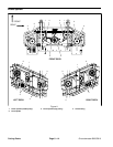
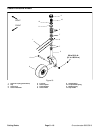
2. Install cutting blade, anti--scalp cup and blade bolt to
spindle. Tighten blade bolt from 88 to 108 ft--lb (119 to
146 N--m).
3. Slowly rotate cutting blades to verify that blades do
not contact any deck components.
4. Install drive beltto spindle pulleysand idler pulley(s).
5. If drive spindle was removed, install hydraulic motor
to cutting deck (see Cutting Deck Motor Installation in
the Service and Repairs Section of Chapter 4 -- Hydrau-
lic Systems).
6. Install covers to cutting deck.
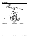
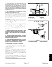
1. Flange head screw 2. Hydraulic motor
Figure 12
1
2
1
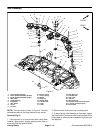
1. Drive spindle
2. Driven spindle
3. Flange head screw
4. Flange nut
5. Cutting blade
6. Anti--scalp cup
7. Blade bolt
8. Flat washer
9. Cap screw
Figure 13
1
2
3
4
5
76
8
9
88 to 108 ft--lb
(119 to 146 N--m)
Cutting Decks