


Groundsmaster 5900/5910 Page 7 -- 13 Chassis
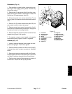
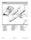
Removal (Fig. 9)
1. Park machine on a level surface, lower cutting
decks, stop engine, apply parking brake and remove
key from the ignition switch.
2. Remove wing deck from lift arm (see Wing Cutting
Deck in Chapter 8 -- Cutting Decks).
3. Remove wing deck impact arm assembly from pivot
hub (see Wing Deck Impact Arm Assembly in this sec-
tion).
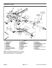
4. Remove joint yoke and cutting deck connection from
lift arm (Fig. 12):
A. Support cutting deck connection to prevent it
from falling.
B. Remove cotter pin, slotted hex nut, hardened
washer and thrust washers from joint yoke shaft.
C. Lower joint yoke, cutting deck connection and
wing deck impact arm assembly from lift arm.
5. Removecap screw and flange nut thatsecure lift cyl-
inder pin (item 5) to lift arm. Slide cylinder pinfrom liftcyl-
inder and lift arm. Separate lift cylinder from lift arm.
6. Remove cap screw (item 23) and flat washer (item
24) from lift arm pivot shaft.
7. Slide wing deck impact arm pivot hub and thrust
washer (item 29) from lift arm pivot shaft.
8. Drive out roll pin (item 22) that retains lift arm pivot
shaft to frame. Discard roll pin.
9. Support lift arm to prevent it from shifting or falling.
Pull lift arm pivot shaft from lift arm and frame. Locate
and remove thrust washer (item 29) during pivot shaft
removal.
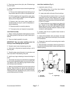
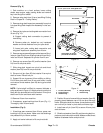
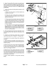
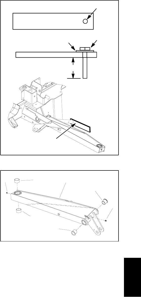
NOTE: If pivot shaft is difficult to remove, fabricate a
puller as shownin Figure 10. Attach pullerto end of pivot
shaft with the pictured bolt and flat washer. Drive pivot
shaft from lift arm and frame with hammer.
10.Remove lift arm from machine.
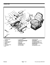
11.If necessary, press bushings from lift arm (Fig. 11).
Thoroughly clean lift arm bores.
Installation (Fig. 9)
1. If bushings were removed from lift arm, press new
bushings into lift arm bores. Make sure that bushings
are pressed fully to lift arm surface.
2. Apply anti--seize lubricant to lift arm pivot shaft.
Figure 10
3” x 12” (3/8” to 1/2” thick) plate steel
9/16” hole
1/2” -- 13 UNC bolt
Flat washer
1” to 1 1/8”
Use hammer to remove
pivot shaft from lift arm
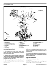
1. Lift arm (LH shown)
2. Flange bushing
3. Grease fitting
4. Straight bushing
5. Grease fitting
Figure 11
2
3
1
4
5
2
4
3. Position lift arm to frame with thrust washer (item 29)
properly placed between rear of lift arm pivot hub and
frame. Slide pivot shaft into frame, thrust washer and lift
arm until roll pin holes in pivot shaft and frame align.
4. Install new roll pin (item 22) to secure lift arm pivot
shaft to frame.
5. Slide thrust washer (item 29) and then wing deck im-
pactarmpivothub onto pivot shaft.Makesurethat thrust
washer is between frame and pivot hub.
Chassis