


Groundsmaster 5900/5910Hydraulic System Page 4 -- 90
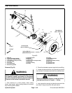
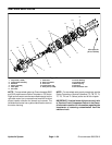
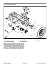
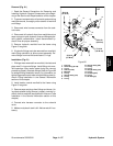
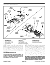
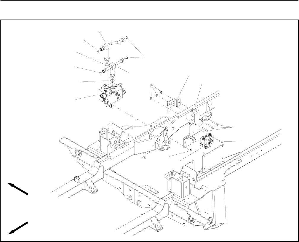
4WD Control M anifold
1. 4WD control manifold
2. O--ring
3. O--ring
4. Hydraulic tee fitting
5. Hydraulic tee fitting
6. Flange nut
7. Bulkhead mount plate
8. Flange nut (2 used)
9. Cap screw
10. Cap screw (2 used)
11. Flush manifold
12. Flange screw (4 used)
Figure 64
6
10
8
2
3
1
11
9
7
12
4
5
2
3
3
FRONT
RIGHT
NOTE: The ports on the 4WD control manifold are
marked for easy identification ofcomponents. Example:
P1 is the pump supply port for the forward direction and
S is the location for the solenoid valve (see Hydraulic
Schematic in Chapter 10 -- Foldout Drawings to identify
the function of the hydraulic lines and cartridge valves
at each port).