


Groundsmaster 5900/5910 Page 7 -- 21 Chassis
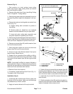
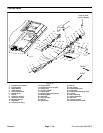
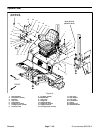
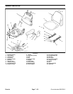
Removal (Fig. 18)
1. Park machine on a level surface, lower cutting
decks, stop engine, apply parking brake and remove
key from the ignition switch.
2. Disconnect seat electrical connector from machine
wire harness.
3. Supportcontrol arm assembly to prevent it from shift-
ing.
4. Remove flange nut (item 12) and carriage screw
(item 16) that secure support bracket (item 13) to sup-
port channel (item 15).
5. Remove cap screw (item 19) and lock washer (item
20) that secure console arm support (item 18) to cou-
pling nut (item 22).
6. Remove cap screw (item 17), two (2) flat washers
(item 2), spacer (item 21) and seat belt buckle (item 23)
from seat and console arm support (item 18).
7. Carefully move console arm assembly away from
seat.
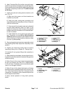
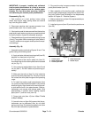
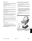
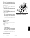
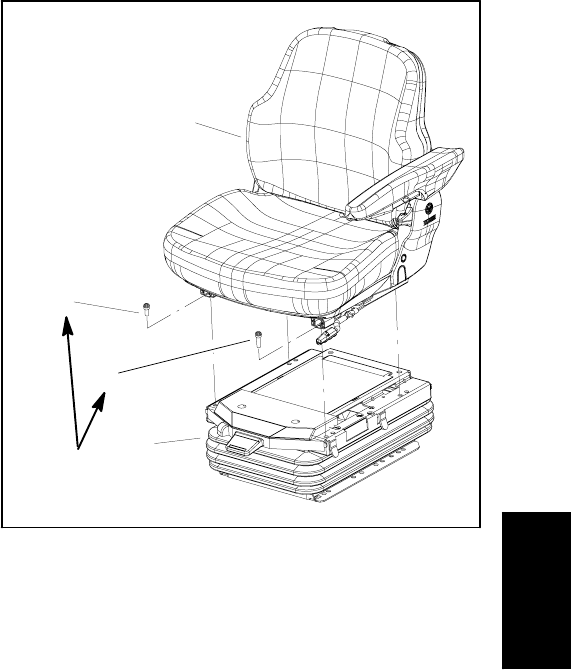
8. Remove four (4) Torx head screws (Fig. 19) that se-
cure seat to seat suspension. Note that the screw near
theseatadjustmenthandleislongerthantheotherthree
screws.
9. Lift seat from seat suspension and remove from ma-
chine.
Installation (Fig. 18)
1. Carefully position seat to seat suspension.
2. Secure seat to seat suspension with four (4) Torx
head screws (Fig. 19). Make sure that longer screw is
positioned near the seat adjustment handle. Torque
screws 18 ft--lb (25 N--m).
3. Position and secure console arm assembly to seat.
Install all fasteners before fully tightening them.
A. Secure support bracket (item 13) and support
channel (item 15) with flange nut (item 12) and car-
riage screw (item 16).
B. Secure console arm support (item18) to coupling
nut with cap screw (item 19) and lock washer (item
20).
C. Place flat washer (item 2), seat belt buckle (item
23) and spacer (item 21) between seat and console
arm support (item 18) and secure with flat washer
(item 2) and cap screw (item 17). Torque cap screw
from 50 to 60 ft--lb (68 to 81 N--m).
D. Fully tighten all fasteners to secure console arm
assembly to seat.
4. Connect seat electrical connector to machine wire
harness.
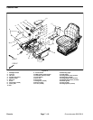
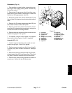
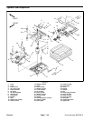
1. Seat
2. Suspension assembly
3. Screw (M8x12) (3 used)
4. Screw (M8x16)
Figure 19
2
3
1
4
18 ft--lb
(25 N--m)
Chassis