


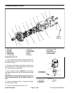


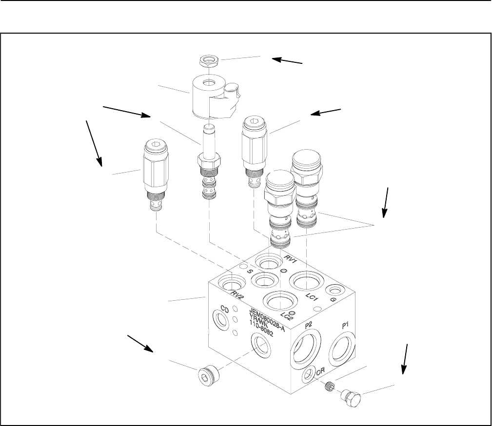
Groundsmaster 5900/5910Hydraulic System Page 4 -- 108
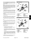
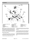
PTO Control Manifold Service
1. Manifold body
2. Relief valve (RV2)
3. Solenoid valve (S)
4. Solenoid coil
5. Nut
6. Relief valve (RV1)
7. Spool logic element (LC1 & LC2)
8. Orifice (OR) (RH and LH only)
9. NWD #4 plug with O--ring
10. NWD #8 plug with O--ring
Figure 81
6
10
8
2
3
1
9
7
4
5
20 ft--lb
(27 N--m)
20 ft--lb
(27 N--m)
50 ft--lb
(67 N--m)
35 ft--lb
(47 N--m)
20 ft--lb
(27 N--m)
5 ft--lb
(6.7 N--m)
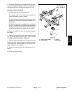
NOTE: The ports on the PTO control manifolds are
marked for easy identification ofcomponents. Example:
Sisthesolenoid valve and M2 is the return from thedeck
motor (see Hydraulic Schematic in Chapter 10 -- Foldout
Drawings to identify the function of the hydraulic lines
and cartridge valves at each port location).
NOTE: ThePTO control manifolds include severalzero
leak NWD plugs. These plugs have a tapered sealing
surface on the plug head that is designed to resist vibra-
tion induced plug loosening. The zero leak plugs also
have an O--ring as a secondary seal. If zero leakplug re-
moval is necessary, lightly rap the plug head using a
punch and hammer before using a wrench to remove
the plug: the impact will allow plug removal with less
chance of damage to the head of the plug. When instal-
ling plugs, refer to manifold illustration in Figure 81 for
plug installation torque.