


Groundsmaster 5900/5910 Cutting DecksPage 8 -- 13
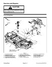
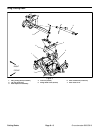
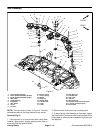
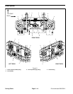
Disassembly (Fig. 9)
1. Park machine on a level surface, lower front cutting
deck, stop engine, apply parking brake and remove key
from the ignition switch.
2. Remove covers from front cutting deck.
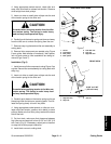
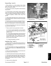
3. Using appropriate socket wrench, rotate idler arm
away from drive belt to release belt tension. Remove
drive belt from deck winglet spindle.
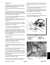
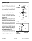
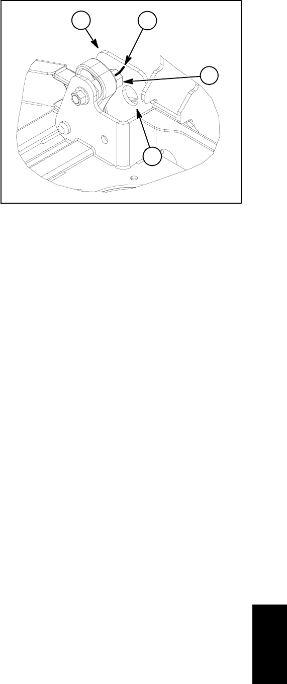
4. For assembly alignment purposes, use a marker or
paint pen on eccentric and deck brackets to identify
location of eccentric (Fig. 10).
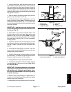
5. Remove lock nut, cap screw, eccentric and hinge pin
from front and rear winglet hinges. Use hole in deck
bracket to remove eccentric from deck. Slide winglet
away from front deck.
6. Inspect hinge pin, eccentric and flange bushings in
deck winglet. Replace worn or damaged components.
Assembly (Fig. 9)
1. Position winglet to front deck.
2. Secure deck winglet to center deck with hinge pin.
3. Position eccentrics in center frame brackets and
install cap screw and lock nut. Do not fully tighten fasten-
ers.
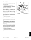
4. Using appropriate socket wrench on idler arm to re-
lease drive belt tension, position drive belt to deck wing-
let s pindle. Make sure that idler pulley tensions the back
side of the belt.
5. Use the marker or paint pen line made during disas-
sembly to position the eccentric (Fig. 10). Check front
deck blade planeand adjust as needed. Refer to Opera-
tor’s Manual for additional adjustment information. After
blade plane is adjusted correctly, tighten lock nut to se-
cure eccentric in position.
6. Lubricate hinge pin grease fittings.
7. Install and secure all removed covers to front cutting
deck.
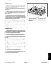
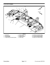
1. Eccentric
2. Deck bracket
3. Marker/paint line
4. Eccentric removal hole
Figure 10
2
1
3
4
Cutting Decks