


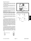


Groundsmaster 5900/5910 Hydraulic SystemPage 4 -- 13
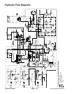
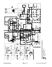
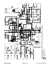
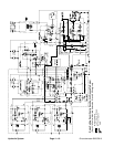
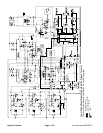
Traction Circuit: Low Speed
A variable displacement, bi--directional piston pump is
directly coupled to the engine flywheel to provide hy-
draulic flow for the traction circuit. The piston pump
swash plate movement is controlled by an electronic
proportional servo assembly. Pushingthe traction pedal
rotates a potentiometer that sends a signal to the ma-
chine TEC--5002 controller. The controller in turn sends
a corresponding PWM (Pulse Width Modulation) output
signal to the hydrostat electronic control to rotate the
pumpswashplateaccordinglytocontrolthepump’s out-
put. The oilfrom the hydrostat is directed to the frontand
rear wheel motors through the traction, 4WD and trac-
tion flush control manifolds.
Operating pressure on the high pressure side of the
closed loop traction circuit is determined by the amount
of load developed at the fixed displacement wheel mo-
tors. As the load increases, circuit pressure can in-
crease to relief valve settings: 4330 PSI (299 bar) in the
forward direction and 5330 PSI (368 bar) in reverse. If
pressure exceeds the relief setting, oil flows through the
relief valve to the low pressure side of the closed loop
traction circuit.
Traction circuit pressure (forward and reverse) can be
measured at test ports located on the hydrostat.
The traction circuit provides operation in either low
speed (four wheel assist) or high speed (two wheel
drive).
The traction pump and wheel motors use a small
amount of hydraulic fluid for internal lubrication. Fluid is
designed to leak across the pump and motor parts and
into the component case drain. This leakage results in
the loss of hydraulic fluid from the closed loop traction
circuit that must be replaced. The charge circuit is de-
signed to replace this traction circuit leakage.
The gear pump section (P3) that supplies oil to the steer-
ing, lift and cooling fan circuits, also provides charge oil
for the traction circuit. The gear pump is driven directly
off the traction pump. It provides a constant supply of
charge oil to the traction circuit to make up for oil that is
lost to internal leakage in the traction pump and wheel
motors. Charge pump flow is directed through the
charge oil filter before entering the hydrostat. This filter
has a bypass valve that allows charge oil flow to the
closed traction loop if the filter becomes plugged.
The charge pressure is limited to 330 PSI (22.8 bar) by
a relief valve located in the hydrostat. Charge pressure
can be measured atthecharge pressure testport (G) on
the hydrostat.
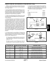
Forward Direction
With the low speed range selected and the traction ped-
al pushed in the forward direction, oil from the hydrostat
port MB passes through the traction control v alve (see
Traction Circuit: Traction Control in this section).Oil flow
from traction controlvalve port M1 drivesthe front wheel
motors in the forward direction and then returns to the
hydrostat. Oil flow from traction control valve port M2 is
routed to the P1 port of the 4WD control valve where it
is directed to the PD1 cartridge and out of the manifold
to drive the rear wheel motors in the forward direction.
Oil returning from the rear motors re--enters the 4WD
control valve at the M2 port. Flow passes through the
PD2 cartridge, through the CV check v alve, out valve
port P2 and back to the hydrostat.
To keep the traction circuit oil properly cooled, a flush
valveisincorporatedintothetractioncircuit.W hen inthe
forward direction, the flush valve spool is shifted by for-
ward pressure and allows a small amount of hydraulic
fluid to bleed offfor cooling ofthe closed loop tractioncir-
cuit. The charge system replenishes oil that is bled from
the traction circuit due to the flushing valve operation.
When going down a hill, the tractor becomes an over--
running load that drives the wheel motors. In this condi-
tion, the rear wheel motors could lock up as the oil
pumped from the motors increases pressure as it re-
turns to the hydrostat. To prevent wheel lock up, an ad-
justable relief valve (RV) in the 4WD control valve
reduces rear motor pressure created in down hill, dy-
namic braking conditions.
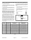
Reverse Direction
The traction circuit operates essentially the same in re-
verse low speed as itdoesin the forward direction.How-
ever, the flow through the circuit is reversed. Oil flow
from the hydrostat port MA is directed to the front wheel
motors and to 4WD control valve port P2. Oil to the front
wheel motors drives them in the reverse direction and
then returns to the hydrostat through the traction control
valve.Oilflowto the 4WDcontrolvalveflowsthroughthe
PR pressure reducing valve which limits the down
stream pressure to the rear wheel motors to 650 PSI (45
bar) so the rear wheels will not scuff the turf. This re-
duced pressure flow passes through the PD2 cartridge
and out portM2to the rear wheelmotors.Return oil from
the rear motors re--enters the 4WD control valve at port
M1, flows through the PD1 cartridge, exits the manifold
at port P1 and returns to the hydrostat through the trac-
tion control manifold.
When in the reverse direction, the flush valve spool re-
mains in the unshifted position to prevent any traction
circuit fluid loss.
Hydraulic
System