


Groundsmaster 5900/5910 Page 5 -- 59 Electrical System
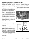
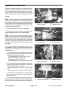
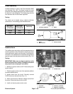
Hydraulic Oil Temperature Sender
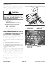
The hydraulic oil temperature sender is attached to the
hydraulic flush manifold in port TS (Fig. 106).
Testing
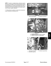
1. Locate oil temperature sender on hydraulic flush
manifold. Disconnect wire harness connector from tem-
perature sender.
2. Thoroughly clean hydraulic flush manifold around
temperature sender. Remove sender from manifold.
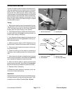
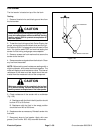
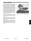
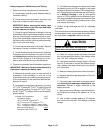
3. Put sensing end of sender in a container of oil with
a thermometer and slowly heat the oil (Fig. 107).
CAUTION
Handle the hot oil with extreme care to prevent
personal injury or fire.
NOTE: Prior to taking resistance readings with a digital
multimeter, short the meter test leads together. The me-
ter will display a small resistance value (usually 0.5
ohms or less). This resistance is due to the internal re-
sistance of the meter and test leads. Subtract this value
from from the measured valueofthe component you are
testing.
4. Check resistance of the sender with a multimeter
(ohms setting) as the oil temperature increases.
A. Themeter should indicate from11.6 to 13.5ohms
at 68
o
F(20
o
C).
B. The meter should indicatefrom 2.3 to 2.5 ohms at
140
o
F(60
o
C).
C. The meter shouldindicate from 0.6 to0.7 ohms at
212
o
F (100
o
C).
D. Replace sender if specifications are not met.
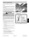
5. After allowing thesender tocool, install senderto the
flush control manifold.
A. Install new O--r ing on sender.
B. Install sender into the hydraulic flush manifold.
Torque sender to 12 ft--lb (16.3 N--m).
C. Reconnect harness wire to s ender.
6. Check and fill hydraulic system to proper level.
Figure 106
1. Hydraulic flush manifold
2. Oil temperature sender
3. Fuel water separator
1
2
3
Figure 107
Electrical
System