


Groundsmaster 5900/5910Page 6 -- 22Axles, Planetaries and Brakes
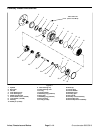
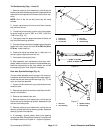
7. Remove the flange head screw, spindle cap and re-
taining ring that secure the steering spindle into the axle
tube. Slide the spindle out of the axle tube to expose the
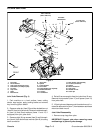
spindle bushings. Locate and retrieve thrust washer
(item 20) from steering spindle shaft.
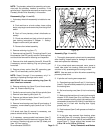
8. Use a bushing removal tool to extract both spindle
bushings from the axle tube. Take care to not damage
the bore of the axle tube. Clean the inside of the axle
tube to remove any dirt or foreign material.
9. Apply grease to the inside and outside of the new
bushings. Use apress to installthe bushings into the top
and bottom of the axle tube. Press bushings into tube
until bushing flange shoulder bottoms on tube.
10.Thoroughly clean the steering spindle shaft. Inspect
the spindle for wear and replace if worn or damaged.
11.Install thrust washer (item 20) onto the spindle shaft
and slide the shaft up through the axle tube. Hold the
spindle shaft assembly in place and install the retaining
ring (item 16) into the groove in the spindle shaft.
12.Install the spindle cap and flange head screw.
13.Thoroughly clean the tapered surfaces of the tie rod
ends, steering cylinder ball joints and steering spindle.
14.Connect the tie rod end to the steering spindle with
slotted hex nut and cotter pin. Torque nut from 35 to 50
ft--lb (48 to 67 N--m).
15.Secure steering cylinder ball joint to steering spindle
with slotted hex nut and cotter pin. Torque nut from 30
to 45 ft --lb (41 to 61 N--m).
16.If removed,install rearwheel motor (see RearWheel
Motor Installation in the Service and Repairs section of
Chapter 4 -- Hydraulic System).
17.Secure rear wheels to axle with lug nuts (see Wheel
Installation in this section).
Failure to maintain proper wheel lug nut torque
could result in failure or loss of wheel and may
result in personal injury.
WARNING
18.Install rear axle to machine (see Rear Axle Installa-
tion in this section). After lowering machine to ground,
torque wheel lug nuts from 70 to 90 ft--lb (95 to 122
N--m).
19.Lubricate the steering spindles through the grease
fittings on the rear axle.
20.Check rear wheel toe--in and adjust if necessary.
21.Operate machine and check hydraulic connections
at steering cylinders and wheel motors for leaks.
22.After assembly and adjustments have been com-
pleted, make sure that no contact is made between any
machine components as the rear wheels are moved
from steering lock to lock. Adjust if necessary.
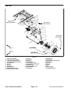
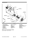
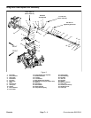
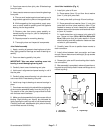
Axle Pivot Bushings (Fig. 14)
The r ear axle must be held in place snugly by the axle
pivot shaft. Excessive movement of the axle, which is
often characterized by erratic steering, might indicate
worn axle pivot bushings. To correct the problem, re-
place the rear axle pivot bushings (Fig. 17).
1. Loosen, but do not remove, lug nuts that secure rear
wheels to axle.
2. Remove rear axle from machine ( see Rear Axle Re-
moval in this section).
3. Remove rear wheels from axle (see Wheel Removal
in this section).
4. Use a bushing removal tool to extract both axle pivot
bushings from the axle pivot tube. Take care to not dam-
age bore of pivot tube during bushing removal.
5. Clean the inside of the tube to remove all dirt and for-
eign material.
6. Apply grease to the inside and outside of the new
bushings. Use a press to install the bushings into the
front and back of the axle pivot tube.Press bushingsinto
tube until bushing flange shoulder bottoms on tube.
7. Secure rear wheels to axle with lug nuts (see Wheel
Installation in this section).
Failure to maintain proper wheel lug nut torque
could result in failure or loss of wheel and may
result in personal injury.
WARNING
8. Install rear axle to machine (see Rear Axle Installa-
tion in this section). After lowering machine to ground,
torque wheel lug nuts from 70 to 90 ft--lb (95 to 122
N--m).