


Reelmaster 2300–D/2600–D Hydraulic SystemPage 4 – 61
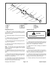
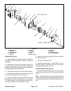
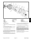
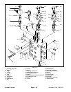
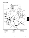
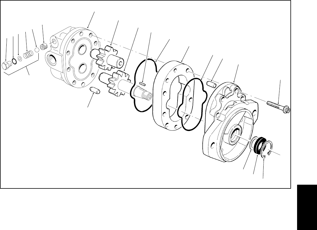
1. Plug
2. O–ring
3. Shim
4. Spring
5. Ball
6. Relief valve seal
7. Backplate
8. Idler gear assembly
9. Drive gear assembly
10. Key
11. O–ring
12. Body
13. Alignment pin
14. Frontplate
15. Screw
16. Retaining ring
17. Oil seal
18. Backup washer
19. Relief valve assembly (# 1 thru 5)
Figure 56
1
2
3
4
5
6
7
8
9
10
16
17
18
19
11
12
13
14
15
11
13
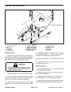
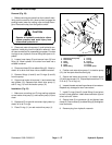
Disassembly (Fig. 56)
1. Make sure key (10) is removed from the drive gear
(9) shaft.
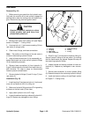
2. Matchmark frontplate (14), body (12), and back-
plate (7) to assure proper reassembly.
3. Secure the motor in a vise with the drive shaft up.
4. Remove all eight screws (15).
5. Remove the motor from the vise. Remove the front-
plate (14) from the body (12). A wooden block or soft
face hammer might be used the gently tap the motor
when freeing the frontplate (14).
6. Remove alignment pin (13) from the body (12). Re-
move drive gear (9) and idler gear (8) from the body (12).
7. Remove body (12) from the backplate (7). Remove
O–rings (11) from the body (12) and backplate (7).
8. Remove Alignment pin (13) from the backplate (7).
9. Remove retaining ring (16), oil seal (17), and back-
up washer (18) from the frontplate (14).
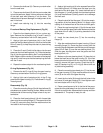
IMPORTANT: Do not remove the relief valve assem-
bly (19) unless testing shows it to be faulty. The re-
lief valve assembly must be replaced as a complete
unit. Both relief valve seals (6) are sealed in place
with loctite; do not remove them.
10. Remove plug (1), O–ring (2), shim (3), spring (4),
and ball (5 ) from the backplate (7).
Hydraulic
System